CNC Machining Tolerances: Optimize Precision, Cost & Manufacturability for Custom‑Machined Parts
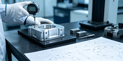
Table of Contents
- What Exactly Are CNC Machining Tolerances?
- Practical CNC Tolerance Reference Table
- Main Tolerance Categories for CNC‑Machined Components
- Tolerance Differences: CNC Milling versus CNC Turning
- Core Terminology for Dimensional & Geometric Tolerancing
- Primary Variables That Shape Achievable Tolerance Levels
- Best Practices to Select Realistic, Cost‑Effective Tolerances
- Why Strict Tight Tolerances Push Up Manufacturing Expenses
- Scenarios Where Tight Tolerances Are Unnecessary
- Tolerance Stack‑Up: When Individually‑Compliant Parts Fail Assembly
- Inspection Approaches to Verify Machining Tolerances
- Industry Standards: ISO 2768, ASME Y14.5, and GD&T
- Partnering with a CNC Supplier to Meet Your Precision Goals
- Closing Thoughts
- Frequently Asked Questions
What Exactly Are CNC Machining Tolerances?
Tolerances define the maximum allowable departure from a part’s nominal drawing dimension. Every machined feature carries some amount of expected variance, and tolerance values establish pass‑fail thresholds for quality validation.
Most dimensional tolerances use the ± symbol. For instance, a nominal dimension of 4.000 in annotated ±0.002 in means acceptable finished measurements sit between 3.998 in and 4.002 in. Any measured value falling outside that window renders the part non‑conforming.
We describe specifications as “tight tolerances” when permitted deviation is very small, demanding superior machine control. “Loose tolerances” permit broader dimensional spread for non‑critical geometry. Tight‑tolerance manufacturing calls for extra set‑up cycles, slower cutting cycles, premium tooling, and enhanced quality checks — all of which raise overall project cost.
Practical CNC Tolerance Reference Table
Real‑world attainable tolerance values shift depending on vendor capability, workpiece material, wall thickness, feature geometry, and batch volume. Most machine shops apply a default general tolerance of ±0.005 in (±0.127 mm) for ordinary metal components when drawing notes do not specify custom limits.
Important note: these figures represent typical real‑world performance under favorable shop conditions, not absolute guarantees. A small rigid aluminum block will consistently hit finer tolerances compared to a large thin‑walled stainless‑steel housing, even using identical machine hardware.
Before finalizing drawing annotations, always cross‑check your target tolerances against your manufacturer’s process capacity, material properties, and inspection resources.
Tolerance Grade Imperial Value Metric Equivalent Typical Application Scenarios General‑purpose default ±0.005 in ±0.127 mm Mount brackets, equipment housings, protective covers, non‑critical structural pieces High‑precision grade ±0.001 in ±0.0254 mm Locating bosses, bearing mounting seats, press‑fit holes, critical mating interfaces Ultra‑precision grade ±0.0005 in ±0.0127 mm Aerospace hardware, medical implant components, optical fixtures, high‑accuracy instrument assemblies Standard angular tolerance ±0.5° Feature‑dependent Chamfers, angled outer surfaces, decorative geometry without alignment requirements Precision angular tolerance ±0.25° or better Feature‑dependent Mating angled faces, angular alignment for moving sub‑assemblies
Main Tolerance Categories for CNC‑Machined Components
Engineers deploy multiple tolerance formats on drawings, each built for distinct functional requirements.
General Default Tolerances
General tolerances apply globally across a drawing via a title‑block note, for dimensions without explicit callouts. This eliminates manually adding tolerance values to every single feature. Shops frequently rely on ISO 2768‑m as a catch‑all baseline for ordinary production parts.
Limit Tolerances
Limit tolerances directly list upper and lower permissible dimensions without a ± modifier. Example:20.0 – 20.4 mm. Any measured result between those two numbers passes inspection. This format delivers unambiguous acceptance boundaries for gauging workflows.
Unilateral Tolerances
Unilateral tolerances restrict variation exclusively to one direction: either all positive or all negative deviation. An example:Φ12 +0.02/‑0.00 mmpermits the hole to grow up by 0.02 mm but cannot shrink below nominal size. This notation is common for press‑fit bores and pin interfaces where over‑size or under‑size conditions would break assembly performance.
Bilateral Tolerances
Bilateral tolerances allow equal positive and negative drift away from nominal dimension, written in ± format. Example:25 ±0.04 mm. This is widely used for outer structural dimensions where minor growth or shrinkage creates no functional risk.
Geometric Dimensioning and Tolerancing (GD&T)
Simple size tolerances only control how big or small a feature may be. GD&T goes further by governing geometry behavior: flatness, concentricity, perpendicularity, true position, profile, and run‑out. Using standardized feature control frames and symbols, GD&T ties features back to defined datum references rather than just isolated dimension values.
For complex assemblies, GD&T often delivers more predictable manufacturability compared to tightening dozens of independent linear dimensions. It is indispensable for high‑reliability sectors including medical equipment and aerospace components.
Tolerance Differences: CNC Milling versus CNC Turning
Both milling and turning deliver high‑accuracy outputs, yet each process has natural strengths and limitations shaped by workpiece geometry and fixturing.
CNC Milling excels for flat faces, pockets, slots, complex 3D contours, drilled holes, and tapped openings. Milling accuracy is heavily influenced by tool overhang, workpiece rigidity, number of re‑fixturing steps, and wall thickness. Deep cavities, ultra‑thin walls, and long slender cutting tools introduce deflection that makes holding fine tolerances more challenging. Multiple set‑ups compound positional error risk.
CNC Turning is optimized for rotationally‑symmetric workpieces: shafts, bushings, pins, threaded parts, and cylindrical sleeves. When parts can be completed within a single chuck setup, turning achieves outstanding consistency for diameters and concentric profiles. However, slender long shafts, interrupted cutting passes, and tough‑to‑machine alloys create vibration and bending that degrade achievable precision.
Keep in mind that geometry frequently matters more than process classification. A simple short aluminum turned shaft will easily sustain ±0.001 in tolerance, whereas a large thin milled plastic cover may struggle to maintain that same specification. Always interpret tolerance tables together with part design context.
Core Terminology for Dimensional & Geometric Tolerancing
Clear mastery of these fundamental terms prevents miscommunication between designers, machinists, and quality inspectors.
- Nominal / Basic Size: The theoretical target dimension printed on engineering drawings. Real manufactured parts will never match this value perfectly.
- Actual Size: The physical measured dimension of a finished component after all machining operations complete.
- Limits: The absolute minimum (lower limit) and maximum (upper limit) dimension permitted for acceptance. Measurements outside these limits reject the part.
- Deviation: The numerical gap between actual measured size and nominal dimension. Upper deviation = upper limit minus nominal size; lower deviation = lower limit minus nominal size.
- Datum: A theoretically perfect reference plane, axis or point selected as the measurement origin. Datums are the backbone of GD&T and control how features relate functionally during final assembly.
Primary Variables That Shape Achievable Tolerance Levels
Many interconnected factors determine what tolerances you can realistically achieve. Simply specifying a tight number on a drawing does not guarantee your supplier can deliver it.
Workpiece Material
Material characteristics exert substantial influence on final precision:
- Abrasive properties: Highly abrasive materials rapidly wear cutting edges. Blunted tools gradually shift dimensional accuracy through the production run.
- Hardness & ductility: Soft ductile materials like copper or certain plastics can spring back after cutting force is removed, making micron‑level control harder. Hardened alloys demand more stable cutting conditions.
- Thermal stability: Heat generated while machining causes thermal expansion. Plastics and some non‑metals are especially prone to thermal distortion, limiting feasible tight‑tolerance features. Metals such as aluminum also expand and contract with temperature fluctuations on the shop floor.
Machining Process & Equipment
3‑axis mills, multi‑axis equipment, and CNC lathes each have distinct capability envelopes. Additional secondary operations such as grinding or reaming are often required to hit ultra‑tight dimensional targets. Every time you re‑fixture a workpiece, you introduce potential positional error.
Post‑Processing Surface Treatments
Anodizing, electroplating, powder coating, and chemical conversion coatings add measurable material thickness onto surfaces. If you define tight tolerances before accounting for coating build‑up, finished dimensions can drift outside your acceptable window. Always budget for surface finishing thickness in your tolerance planning.
Cutting Tool Selection
Tool material, coating, sharpness, and geometry directly affect output consistency. Worn, chipped, or overly long tools generate tool deflection and dimensional scatter. High‑precision jobs demand scheduled tool changes throughout batch production.
Operator & Programming Expertise
Experienced machinists select appropriate feeds/speeds, optimize tool paths, implement in‑process metrology, and mitigate workpiece vibration. Even premium machinery yields inconsistent results without competent setup and programming.
Budget & Volume Expectations
Tighter tolerances consume more machine time, tooling, and inspection labor. For high‑volume batches, consistent tight tolerances demand process validation and statistical quality monitoring, further raising overall project costs.
Best Practices to Select Realistic, Cost‑Effective Tolerances
Adopt these actionable recommendations when annotating drawings for CNC production:
- Adjust expectations for material behavior: Standard ±0.005 in works well for most rigid metal parts. Plastics generally require looser baseline tolerances, such as ±0.010 in, due to deflection and thermal movement. Materials sensitive to temperature swings need adjusted limits to compensate for expansion and contraction.
- Base tolerances on component function: Ask yourself: will variation in this dimension interfere with fit, sealing, motion, or safety? Reserve strict tolerances exclusively for features where performance depends on them. Decorative or non‑mating surfaces can safely use general drawing tolerances.
- Main sharp cutting tools and adequate coolant: Tool deflection on deep holes or extended shafts is a frequent source of dimensional drift. Sharp tools paired with proper cooling minimize thermal distortion and workpiece spring‑back.
- Engage your manufacturing supplier early: Early DFM (Design for Manufacturability) consultation allows you to validate whether your tolerance targets are practical before quotation. Clearly list special tolerance and inspection requirements when you submit CAD files and 2D drawings.
Why Strict Tight Tolerances Push Up Manufacturing Expenses
Demanding very narrow tolerance windows ripples through every production stage:
- Cutting parameters must slow down; parts often require sequential roughing, semi‑finishing, and finishing passes rather than single‑pass machining.
- Custom fixtures, repeated re‑fixturing, and frequent in‑process dimensional checks become mandatory. Tools must be replaced more frequently to stop dimensional drift from tool wear.
- Inspection complexity rises. Basic calipers and micrometers may no longer suffice; high‑precision jobs may need bore gauges, pin gauges, surface roughness testing, or CMM (Coordinate Measuring Machine) reporting. In extreme cases, every single component must receive full inspection rather than sampling.
- Scrap rates increase. Even minor normal process variation can push features outside narrow tolerance bands.
Over‑tolerancing — assigning tight limits to dimensions that serve no critical purpose — remains one of the top drivers of unnecessary CNC project expense.
Scenarios Where Tight Tolerances Are Unnecessary
Tighter is not always better. There are multiple common situations where strict tolerances deliver zero added value:
- Components fabricated from materials exhibiting high thermal expansion, including acrylic plastics, polyethylene, and aluminum alloys.
- Assembly interfaces intentionally designed to accept moderate clearance for easier part fitting.
- Consumer‑grade goods where minor dimensional fluctuation will not alter functionality or durability.
- Purely cosmetic features, engraving, or decorative cutouts with no mating role.
- Cost‑sensitive projects where tightening tolerances provides no tangible performance improvement.
Tolerance Stack‑Up: When Individually‑Compliant Parts Fail Assembly
Tolerance stack‑up describes the cumulative effect of many small allowable deviations across a dimension chain. Each separate component may pass individual QC checks, yet when assembled together, accumulated variance creates misalignment, binding, or excessive clearance.
Example: multiple bolt holes all within their individual size tolerances, but combined positional error shifts hole patterns enough to prevent bolt insertion. A shaft and housing may each satisfy independent dimensional limits, yet combined worst‑case variation yields either too‑tight interference or excessive play.
You can mitigate stack‑up risk by:
- Mapping the complete dimension chains that govern assembly fit early in design work.
- Applying worst‑case tolerance analysis for simple assemblies, or statistical tolerance analysis for larger‑scale production.
- Deploying GD&T tied to functional datums instead of chaining many independent linear dimensions.
When two “in‑spec” components refuse to assemble, poor tolerance design — not machining quality — is usually the root cause.
Inspection Approaches to Verify Machining Tolerances
A tolerance specification carries little practical weight unless you can reliably measure it. Different inspection hardware matches different feature types and accuracy demands:
- Calipers: Suitable for general‑purpose dimension checks; insufficient for ultra‑tight micron‑level requirements.
- Micrometers: Excellent for precise measurement of outer diameters and thickness.
- Pin gauges / plug gauges: Fast go‑no‑go validation for hole diameters.
- Bore gauges: Deliver higher‑accuracy internal diameter readings compared to calipers.
- Height gauges (on surface plates): Inspect step heights, depths, and relative positional offsets.
- CMM (Coordinate Measuring Machine): The gold standard for complex geometry, true‑position verification, flatness, profile, and multi‑datum geometric measurements.
- Surface roughness testers: Required whenever surface finish Ra values are specified.
Measurement environment matters significantly. Precision metrology ideally takes place near the reference temperature of 20 °C. Hot parts straight off the CNC machine or large shop‑floor temperature swings will skew measurement readings.
For high‑stakes components, buyers commonly request First Article Inspection (FAI), full CMM dimensional reports, material certification documents, or statistical process output. As tolerances grow tighter, your inspection plan grows equally important.
Industry Standards: ISO 2768, ASME Y14.5, and GD&T
Global manufacturing standards create shared language between designers, machine shops, quality teams, and procurement.
ISO 2768: The widely‑adopted international standard for general linear and angular tolerances for drawings without dimension‑specific annotations. ISO 2768‑1 addresses length and angle tolerances; ISO 2768‑2 covers basic geometric tolerances. Grade “m” (medium) represents the most common baseline for general CNC parts.
ASME Y14.5: Dominant GD&T standard used throughout North America. It defines rules for datum selection, position, flatness, perpendicularity, run‑out, profile, and other geometric controls.
ISO 1101: International counterpart standard for geometric product specifications and tolerancing (GPS).
Standards remove interpretive ambiguity, but they cannot replace supplier capability assessment. For mission‑critical features, discuss requirements during quotation and confirm both manufacturing workflow and inspection methodology before production launches.
Partnering with a CNC Supplier to Meet Your Precision Goals
Selecting a competent manufacturing partner simplifies hitting your tolerance objectives. Look for suppliers that offer multi‑axis milling, mill‑turn capability, comprehensive secondary surface finishing, and formal quality control workflows including dimensional reporting, material traceability, and first‑article validation.
Share both your 3D CAD files and annotated 2D drawings that spell out tolerance, GD&T, and inspection requirements. Clear documentation prevents costly misinterpretation of design intent.
Closing Thoughts
Tolerances form the foundation of successful CNC‑machined component development. Thoughtfully‑defined tolerances balance performance, manufacturability, lead‑time, and project budget. Achieving good results requires you to consider material behavior, geometry constraints, process limits, assembly stack‑up effects, and inspection capacity.
The most effective tolerance strategy follows function‑first principles: tighten specifications only for features that directly impact fit, safety, or operation, while letting non‑critical geometry rely on proven general standards.
Frequently Asked Questions
What is the baseline standard tolerance for CNC machining?
The common shop‑floor default is ±0.005 in (±0.127 mm). This is a typical reference value rather than universal law. Actual achievable results depend on supplier equipment, material, part size, geometry complexity, and inspection protocols.
How fine can CNC machining tolerances realistically go?
Standard precision CNC work reliably achieves ±0.001 in (±0.0254 mm). Under ideal conditions with stable material, rigid geometry, and dedicated inspection workflows, select features can reach ±0.0005 in (±0.0127 mm). These ultra‑tight values cannot be assumed for every part.
Can every CNC part hit ±0.001 in tolerance?
No. While attainable in many precision scenarios, thin‑wall structures, flexible plastics, large workpieces, deep cavities, heat‑sensitive materials, and complex multi‑set‑up geometry make ±0.001 in impractical or prohibitively expensive. Validate feasibility with your manufacturer early.
Are tighter tolerances always better quality?
Absolutely not. Unnecessary tight tolerances extend machining cycles, raise inspection costs, increase scrap probability, and lengthen lead times. Apply strict limits exclusively for features influencing fit, assembly, safety, or functional performance.
Can you machine CNC components using only a 3D CAD model without 2D drawings?
Simple geometries can sometimes be produced from CAD data alone. Nevertheless, critical tolerances, GD&T call‑outs, surface finish requirements, and special inspection instructions cannot be fully encoded within most 3D files. A properly annotated 2D drawing is strongly recommended for precision‑demanding projects.
When should CMM inspection be specified?
CMM inspection is recommended for complex geometry, demanding geometric tolerances, true‑position requirements, multi‑datum features, aerospace hardware, medical components, automotive safety‑related parts, and any application requiring high‑reliability performance.