Blind Holes in Machining: Definition, Fabrication Workflow and Practical Design Advice

What Exactly Is a Blind Hole?
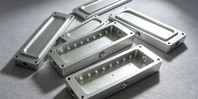
A blind hole (also named pocket hole) is a recessed cavity machined to a preset depth without penetrating all the way through the workpiece substrate. It can be produced by drilling, milling or reaming. One opening sits on the part surface, while the opposite end remains sealed inside the material body.
Since you cannot peer through the feature, it earns the name “blind”. Engineers adopt blind holes to create hidden seating positions for screws, locating pins, fasteners and other assembly hardware. This feature appears in both metal and wood components. For high‑precision sectors, blind holes enable complex internal geometries while preserving mechanical robustness and clean external surfaces of finished parts.
Drawing Annotation for Blind Holes
Engineering drawings use standardized annotation conventions to communicate blind‑hole specifications clearly for workshop teams. A proper callout delivers complete information including hole position, nominal diameter, total machining depth, thread pitch and fastener sizing. Clear drawing notes eliminate misinterpretation of design intent and prevent dimension‑related mistakes during production. Without unambiguous marking on blueprints, machinists risk wrong depth, incorrect bore size or improperly formed internal threads.
Step‑by‑Step Workflow for Drilling High‑quality Blind Holes
Accurate blind‑hole production demands strict control over depth, hole alignment and chip removal. Follow this practical sequence to achieve consistent outcomes.
1. Secure and prepare the raw workpiece
Clamp or fasten the workpiece firmly in a vise to stop shifting or deflection during cutting operations. Mark the hole centre position on the surface with a centre punch or sharp scribe. This indentation guides drill‑bit tip and prevents tool wandering at the start of drilling, which is critical for positional accuracy.
2. Select and install suitable cutting tools
Match drill‑bit diameter to the target hole dimension. Fit the selected bit securely into the drill chuck and tighten it fully. Double‑check tool alignment to avoid wobbling, run‑out and hole deviation throughout cutting. Always pick tool materials adapted to your target workpiece material (metals, plastics or composites).
3. Set your target drilling depth
Calculate the travel distance from drill tip down to the intended bottom of blind cavity. You can wrap tape around the drill shank as a quick visual marker for manual equipment. On drill presses or CNC setups, mechanical depth collars or programmed Z‑axis limits serve as more reliable depth stops to avoid over‑drilling that weakens remaining base material.
4. Perform drilling while monitoring depth status
Position drill tip over your pre‑marked centre spot. Apply steady, moderate downward feed pressure and maintain stable spindle speed. Begin cutting slowly to create a pilot hole; ramp up rotation speed gradually as penetration increases. Pause periodically to verify current depth with depth gauges or reference markers on the tool. Do not rush the feed rate, especially for deep blind features.
5. Remove chips and debris frequently
Unlike through holes, blind cavities trap chips inside the closed bottom. Pull the drill bit back out regularly during drilling cycles to clear away swarf. Common chip‑clearing approaches include flushing with compressed air, coolant liquid streams or utilising drill flutes to lift debris outward. Trapped chips scratch bore walls, generate excess heat and even cause tool fracture if left unaddressed.
6. Complete machining and carry out inspection
Drill until reaching the pre‑defined target depth. Apply secondary finishing operations such as reaming or light boring when smoother inner surface quality is required. Once drilling finishes, inspect the finished hole: validate actual diameter and depth against drawing tolerances. Check for burrs and sharp edges that need deburring before subsequent processes like tapping or assembly.
Core Advantages and Drawbacks of Blind Holes
Key Benefits
-
Superior visual performance: Fasteners sit concealed within blind recesses, eliminating protruding hardware. This characteristic is highly valued for automotive assemblies and consumer‑electronic housings where surface aesthetics carry high priority.
-
Enhanced mechanical performance: Well‑designed blind holes distribute loads evenly across components. They help minimise stress‑riser points and extend service life of workpieces by avoiding full penetration that would break structural continuity.
-
Space‑saving lightweight structures: For aerospace and compact electronic hardware, blind‑hole layouts support miniaturised part design. Designers cut down overall component weight while optimising limited installation space inside devices.
Main Limitations
-
Difficult chip clearance: Chips tend to stack up at sealed hole bottoms. Insufficient chip evacuation leads to overheating and surface defects. Inspection and full cleaning become harder because there is no opening on the far side for direct visual access.
-
Higher tapping difficulty: Creating internal threads inside blind holes is more demanding compared with through‑hole tapping. Operators must carefully manage thread uniformity and avoid driving taps hard against the hole base, which may break tap tools.
-
Risk of workpiece distortion: Under cutting heat and mechanical pressure, materials including aluminium, low‑carbon steel and ABS plastic are prone to local deformation surrounding blind‑hole openings, potentially ruining dimensional stability of parts.
Typical Real‑world Applications of Blind Holes
-
Aerospace manufacturing: Blind‑hole features build lightweight aircraft structural parts without sacrificing overall component strength, supporting weight‑reduction targets for aviation hardware.
-
Electrical and electronic hardware: On circuit boards, blind holes form mounting bases for stand‑offs, connectors and spacers. They enable firm attachment without damaging circuit traces located on opposite board surfaces.
-
Artwork and architectural fabrication: Both metal‑working and wood‑working crafts leverage blind holes for decorative purposes. Manufacturers fill recessed cavities with epoxy resin or metallic inlays to deliver distinctive visual effects.
-
Mould‑making industry: In injection mould and die production, blind holes provide installation positions for ejector pins, cooling passages and alignment features. They improve mould operation stability and final moulded‑part quality.
-
Automotive sector: Engine blocks and transmission components utilise blind holes for secure assembly joints while lowering raw‑material consumption of cast or machined automotive parts.
Practical Tips for Reliable Blind‑hole Machining
-
Choose proper drills and taps: Select tool grades matching workpiece materials. High‑speed‑steel tools work well for threading most metal materials. Match tap dimension with required thread specification. When tapping blind holes, carefully decide among plug taps, taper taps or bottoming taps according to hole depth and thread requirements.
-
Respect depth clearance rules: Always mark or program depth limits to prevent excessive penetration that compromises residual wall strength. Use depth stops on drill equipment and strictly follow drawing‑specified dimensions. Confirm depth setting before starting every batch of parts.
-
Reasonable hole placement and orientation: Use layout squares and centre punches to mark hole locations precisely. Plan hole orientation so finished blind holes fit seamlessly into later assembly workflows; poor placement will hurt manufacturability and part functionality.
-
Confirm hole diameter beforehand: Refer to drill‑bit reference charts for bit selection. Run test drilling on scrap material of identical substrate before processing formal workpieces to verify bore size and cutting behaviour.
-
Thorough internal cleaning before secondary operations: Apply cutting fluid or lubricant to lower friction and heat accumulation during drilling. Use brushes or compressed air to expel chips out of cavities. Make certain blind holes are fully cleaned before tapping to prevent thread damage from trapped debris.
Blind Hole vs Through Hole: Core Differences
Feature
Blind Hole
Through Hole
Penetration status
Terminates at internal depth; bottom closed
Fully pierces workpiece, two open ends
Primary purpose
Hidden fastener seating, preserve reverse‑side appearance or sealing
Pass‑through installation for bolts, pins with nuts or washers fitted on opposite side
Manufacturing complexity
Higher: strict depth control, difficult chip evacuation
Simpler: chips can exit out the far opening freely
Typical scenarios
Automotive appearance parts, consumer electronics, sealed housings
General mechanical assembly, alignment structures requiring full‑length fastener passage
Other Common Hole Types in Machining
Beyond blind and through holes, subtractive manufacturing utilises multiple hole geometries for diverse engineering needs:
-
Simple hole: Straight cylindrical bore with constant diameter running through workpiece thickness, widely used for clearance fit and component positioning.
-
Reamed hole: Post‑processed by reamer tools to achieve precise dimension and smooth inner‑wall surface finish.
-
Countersunk hole: Conical recess that lets screw or bolt heads sit flush with component outer surface.
-
Counterbore hole: Flat‑bottomed cylindrical enlarged recess, creating seating planes for socket‑head fasteners.
-
Tapped hole: Internal threads cut by tap tools to realise screw‑based fastening connections. Can be blind or through style.
-
Tapered hole: Diameter gradually changes along hole axis, frequently applied for press‑fit assembly joints.
Conclusion
Blind holes serve as indispensable mechanical features across modern manufacturing. They deliver hidden fastening points, optimise component aesthetics and maintain structural integrity. Nevertheless, fabricating blind holes demands careful handling of depth control, chip removal and tapping processes. Designers and machinists need to weigh benefits against manufacturing challenges at the DFM (Design for Manufacturability) phase, specifying blind holes only when functional requirements truly justify their extra production complexity.
Frequently Asked Questions
Q: What is a threaded blind hole?
A threaded blind hole carries internal threads but does not run through the full workpiece thickness. Threaded recesses create robust joining interfaces for mating hardware without opening through to the opposite side of the component.
Q: Which materials can blind holes be machined into?
Blind‑hole machining applies to metals, plastics and composite substrates. Still, material properties dictate optimal cutting parameters, tool selection and achievable depth‑diameter ratios for each application.
Q: How do manufacturers measure and inspect finished blind holes?
Quality teams deploy depth micrometers, plug gauges, coordinate‑measuring machines (CMM), surface profilometers and non‑destructive testing tools. These metrology solutions validate depth, bore dimension and internal surface condition for blind‑hole features that cannot be directly viewed through the part.