Unilateral vs. Bilateral Tolerance in Mechanical Engineering Drawings
Understanding Engineering Tolerances
Every manufacturing process introduces inherent variation. No machined part can perfectly match its nominal dimension every single time. Engineering tolerances define the acceptable upper and lower bounds within which a part’s dimension can vary while still performing as intended.
Consider a bolt that must slide through a drilled hole. If the bolt diameter is too large, it will not fit. If it is too small, the assembly will rattle and lose alignment. Tolerances ensure parts interchange properly, control production costs, and maintain functional performance across every unit produced.
Engineers communicate these requirements through technical drawings, and unilateral and bilateral tolerances are the two most widely used formats for specifying dimensional limits.
What Is Unilateral Tolerance?
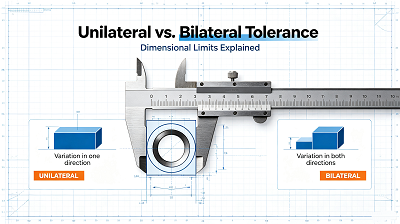
A unilateral tolerance permits dimensional variation in only one direction from the nominal value. The part may be larger or smaller than the nominal size, but not both. One side of the tolerance band sits exactly at the nominal dimension, while the entire allowable deviation falls on the opposite side.
This approach is chosen when functional requirements demand that variation be constrained to a single direction. For example, a design may allow a feature to be slightly undersized but never oversized, or vice versa.
Unilateral Tolerance in Production
Press-fit dowel pins are a classic use case. A dowel pin must fit securely into its hole to maintain precise alignment between two mating components. If the pin diameter exceeds the hole diameter, assembly becomes impossible or damages the part. However, a slight reduction in pin diameter is acceptable as long as the fit remains within functional limits.
By applying a unilateral tolerance, engineers clearly communicate this critical constraint to machinists and quality inspectors, reducing ambiguity on the shop floor and streamlining inspection workflows.
Real-World Unilateral Tolerance Example
On an engineering drawing, a unilateral tolerance is written with a zero deviation on one side.
Suppose a bore has a nominal diameter of 20.0 mm with a unilateral tolerance of +0.08 / -0.00 mm.
Here, the lower deviation is zero, meaning the bore must never be smaller than 20.0 mm. The entire tolerance band sits above the nominal value. The acceptable finished dimension ranges from 20.00 mm to 20.08 mm.
This ensures the bore is always large enough to accept its mating shaft, while preventing excessive clearance that would degrade alignment.
What Is Bilateral Tolerance?
Bilateral tolerance allows dimensional variation on both sides of the nominal value. The part can be either larger or smaller than nominal, within defined upper and lower limits.
The deviation values on each side may be equal (symmetric) or different (unequal), depending on design needs.
Bilateral tolerancing is the most natural representation of manufacturing variation, since real-world processes naturally produce scatter in both directions from the target dimension.
Bilateral Tolerance in Production
Gear teeth spacing is a typical bilateral tolerance application. For a gear set to mesh smoothly and quietly, each tooth must sit at a precise distance from its neighbors.
Deviating too far in either direction—too close or too far apart—causes binding, accelerated wear, or backlash. A bilateral tolerance controls variation on both sides of the nominal pitch to ensure quiet, reliable operation.
Bilateral tolerances also simplify tolerance stack-up analysis in assemblies, making them a staple in complex mechanical systems.
Symmetric Bilateral Tolerance Example
In symmetric (equal) bilateral tolerancing, the plus and minus deviations are identical, so the tolerance band is centered perfectly on the nominal dimension.
For example, a shaft diameter specified as 8.000 ± 0.005 mm is a symmetric bilateral tolerance.
The acceptable dimensional range is 7.995 mm to 8.005 mm. The ± symbol is the standard drawing notation for equal bilateral tolerance.
Unequal Bilateral Tolerance Explained
Unequal (asymmetric) bilateral tolerance uses different plus and minus values. The tolerance band still exists on both sides of nominal, but it is offset toward one side.
For instance, a surface profile might be specified as +0.06 / -0.02 mm relative to the nominal profile. The total tolerance width is 0.08 mm, with three-quarters of the allowance above the ideal surface and one-quarter below.
This format gives engineers finer control when functional performance is more sensitive to deviation in one direction, but some variation in the other direction is still permissible.
Side-by-Side Comparison
The table below summarizes the core distinctions between unilateral and bilateral tolerancing.
| Comparison Category | Unilateral Tolerance | Bilateral Tolerance |
|---|---|---|
| Direction of Variation | Allowed in only one direction from nominal | Allowed in both directions from nominal |
| Typical Notation | +0.04 / -0.00 mm | ±0.04 mm |
| Core Design Goal | Prevents failure by eliminating variation on the critical side | Balances natural manufacturing scatter with functional requirements |
| Manufacturing Difficulty | More restrictive; tighter process control required | More flexible; easier to center production processes |
| Common Use Cases | Fits, alignment features, threaded holes | General dimensions, gear pitches, housing features |
Additional Tolerancing Methods
Beyond unilateral and bilateral formats, several other tolerancing systems are used in mechanical engineering.
- Limit Tolerance: States the maximum and minimum dimension directly, such as 49.95 mm – 50.05 mm, without referencing a nominal value. This format is common on production drawings where operators work directly to boundary values.
- Fit System Tolerances (Hole/Shaft Basis): Standardized tolerance classes (such as H7/g6) define specific clearance, transition, or interference fits between mating holes and shafts according to ISO or ANSI standards.
- Geometric Tolerances (GD&T): Controls form, orientation, location, and runout characteristics independent of size. Examples include flatness, perpendicularity, position, and total runout.
Precision Tolerancing for Custom Manufacturing
At our precision manufacturing facility, advanced CNC machining and metrology equipment ensure tight, repeatable tolerances for prototyping and low-volume production. Our engineering team works directly with clients to select the optimal tolerancing strategy—balancing performance, manufacturability, and cost. From simple bilaterally dimensioned brackets to precision unilateral-fit assemblies, we apply rigorous quality control to deliver parts that print to specification on every run.
Final Thoughts
Unilateral and bilateral tolerances are fundamental tools in the mechanical engineer’s toolkit. Neither is universally superior; each excels in specific scenarios. Unilateral tolerance protects critical functional boundaries, while bilateral tolerance accommodates natural process variation. Selecting the right method—and applying it correctly on engineering drawings—improves manufacturability, reduces scrap, and ensures parts perform reliably in service.
Frequently Asked Questions
Which tolerance type is more accurate?
Accuracy depends on the total tolerance width, not whether it is unilateral or bilateral. A tight bilateral tolerance can be more precise than a wide unilateral one. The choice is about direction of variation, not overall precision.
When should I use unilateral tolerance?
Can unilateral and bilateral tolerances be used in the same drawing?