CAM for CNC Machining:Guide to Processes, Benefits and Best Practices
What is CAM in CNC Machining?
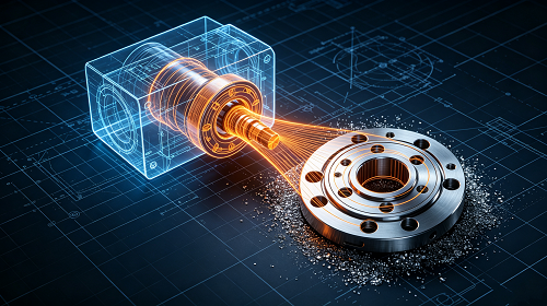
Computer-Aided Manufacturing (CAM) refers to the use of specialized software and computer systems to generate detailed operational instructions that direct CNC machine tools throughout the production process. It takes digital design files created in CAD software and converts them into actionable machine commands that control every movement of cutting tools, spindles, and workholding devices.
The core output of CAM programming is machine-readable code — most commonly G-code — that dictates exact coordinates, feed rates, spindle speeds, tool changes, and cutting paths. When loaded onto a CNC machine, this code automates material removal operations such as milling, turning, and drilling, delivering uniform results even for highly complex geometries. Whether producing a single custom prototype or thousands of production parts, CAM technology ensures repeatable accuracy, minimizes manual intervention, and reduces material waste across every production run.
The Step-by-Step CAM Machining Workflow
Before CAM technology became widespread, manufacturing engineers relied on manual setup, handwritten programs, and custom jigs to guide machine operations — a slow process prone to human error. Modern CAM machining follows a structured digital workflow that connects design directly to production. Here is how the process unfolds:
-
3D CAD Model CreationThe process begins with a complete 3D digital model of the part, created in CAD software. This model contains all geometric dimensions, tolerances, and material specifications required for production.
-
File Import into CAM SoftwareA manufacturing engineer imports the finished CAD file into a CAM programming environment, where the part geometry is prepared for machining planning.
-
Machining Strategy Definition and Toolpath GenerationThe CAM programmer defines production parameters — including workpiece material, cutting tools, fixture setup, and machining sequences. The software then calculates optimized toolpaths based on these inputs, determining exactly how the cutting tool will traverse the part to remove material efficiently.
-
Post-Processing to Machine CodeOnce toolpaths are validated, the CAM system runs a post-processor that converts the generic toolpath data into a specific G-code format compatible with the target CNC machine model and controller.
-
Machine Setup and Code ExecutionThe machine operator loads the generated code onto the CNC machine, secures the raw workpiece, installs the required cutting tools, and initiates the machining cycle. The machine follows the programmed instructions automatically.
-
Finished Part ProductionAfter completing all machining operations, the final part matches the original CAD design with high dimensional accuracy, ready for inspection, secondary finishing, or assembly.
Key Advantages of Integrating CAM with CNC Machining
The adoption of CAM technology transforms CNC machining operations on multiple levels, delivering measurable improvements across productivity, quality, and cost performance.
Greater Design Flexibility
Boosted Production Efficiency
Superior Precision and Part Consistency
Minimized Material Waste
Common CAM-Controlled Machining Processes
CAM software can program a wide range of CNC machine types, each suited for specific part geometries and manufacturing requirements. Below are the most widely used CAM machining processes.
CAM Milling
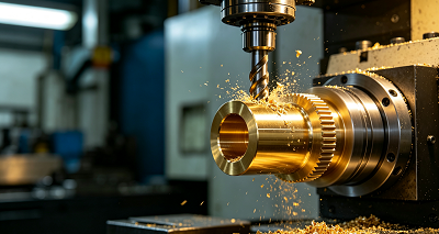
Milling uses rotating multi-edge cutting tools to remove material from a stationary workpiece. CAM programming enables CNC mills to produce highly complex shapes, pockets, slots, and 3D surfaces with tight tolerances. Common milling operations include face milling, profile milling, pocketing, and 3D contour machining — all widely used in aerospace, automotive, and general engineering sectors.
CAM Turning
CAM Drilling
Primary Challenges in CAM Machining Implementation
Despite its many benefits, implementing and operating CAM machining systems presents several challenges that manufacturers must address.
Upfront and Ongoing Costs
CAM technology requires significant initial investment in software licenses, powerful computer hardware, and CNC machine equipment. Additionally, ongoing expenses include software subscriptions, annual maintenance, tooling replacement, and periodic system upgrades.
Programming Complexity for Advanced Geometries
System Downtime and Software Errors
Skilled Workforce Requirements
Critical Considerations and Industry Best Practices
To maximize the performance, reliability, and safety of CAM machining operations, manufacturers should follow these established guidelines.
Evaluate Material Machining Characteristics
Different materials respond very differently to cutting forces, heat, and tool wear. Understanding properties such as hardness, abrasiveness, thermal conductivity, and chip formation helps engineers select appropriate cutting parameters, tool materials, and coolant strategies for optimal results.
Verify CAD/CAM System Compatibility
Select and Maintain Cutting Tools Properly
Simulate and Validate Toolpaths Before Production
Perform Regular Machine Calibration
Industry Applications of CAM Machining Technology
CAM-powered CNC machining plays a vital role across numerous industries where precision, complexity, and consistency are essential.
Aerospace
The aerospace sector depends on CAM to produce structural components, turbine blades, engine mounts, and airframe parts that must meet extremely tight tolerances and rigorous safety standards. CAM’s ability to machine advanced alloys and composites reliably makes it indispensable in this field.
Automotive
Electronics
Medical Device
Partner with Experts for Precision CNC Machining Solutions
When your project demands the highest level of CNC machining precision, working with an experienced manufacturing partner ensures you unlock the full potential of CAM technology. Our team of skilled engineers and machinists combines advanced CAM software with state-of-the-art CNC equipment to deliver accurate, cost-effective parts for prototyping and production alike.
From initial design feedback to final inspection, we apply proven CAM methodologies to optimize every machining operation — reducing lead times, improving part quality, and helping you bring products to market faster.
Final Thoughts
CAM technology has become an indispensable element of modern CNC machining, reshaping how manufacturers translate digital designs into physical products. By automating programming, improving accuracy, reducing waste, and enabling complex geometries, CAM systems elevate manufacturing efficiency and quality across every industry.
As machining technology continues to advance, investing in CAM capabilities and following industry best practices will remain essential for manufacturers seeking to stay competitive, meet evolving customer demands, and maintain the highest production standards.
Frequently Asked Questions
Which CAM software programs are most widely used in the machining industry?
Several leading CAM platforms dominate the market, each with strengths in different application areas. Popular options include Mastercam, Siemens NX CAM, Autodesk Fusion 360, GibbsCAM, SolidCAM, and HyperMill — chosen based on machine compatibility, industry focus, and specific feature requirements.
How does CAM differ from CAD and CAE in the product development cycle?
CAD focuses on creating the digital design and geometry of a part. CAE uses the CAD model to perform engineering analysis such as stress testing, thermal simulation, and motion studies. CAM then takes the validated
CAD model and generates the machine instructions required to physically produce the part. Together they form a connected digital product development workflow.
What core components make up a complete CAM system?
A functional CAM system includes three essential elements: the CAM software itself, which designs and calculates machining toolpaths; the CNC machine hardware, which executes the physical cutting operations; and the post-processor, which translates generic toolpath data into machine-specific control code that the equipment can understand and execute.