Step Turning vs Taper Turning: Core Machining Differences, Processes & Industry Use Cases
1. Basic Overview of Turning Machining
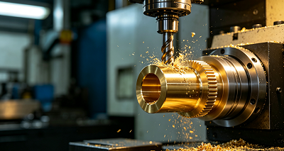
Turning relies on high-speed rotation of a clamped workpiece, paired with a single-point cutting tool to strip excess material and form target rotary profiles. Traditional engine lathes, turret lathes and multi-axis CNC turning centers all support turning operations.
The inherent rotary motion of the workpiece naturally generates cylindrical and conical geometries. Advanced CNC systems further expand processing capacity to complex combined contours, threads and grooves. Step turning and taper turning are the most frequently applied basic turning subtypes, each built for entirely different part geometric requirements.
2. What Is Step Turning?
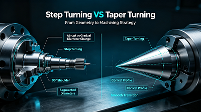
Step turning is the most entry-level, straightforward lathe machining method. It fabricates multi-stage cylindrical workpieces with abrupt diameter changes along the workpiece’s central axis. Each independent segment (called a "step") maintains a fixed uniform diameter, with sharp perpendicular shoulder transitions between adjacent diameters.
The cutting tool’s feed path runs strictly parallel to the workpiece central axis throughout the entire cutting cycle. The stepped profile resembles stair treads, hence the name "step turning".
Core Functional Value of Step Profiles
- Create positioning shoulders for bearing, gear and sleeve assembly to restrict axial sliding of mating parts
- Design distinct diameter seats for multi-component stacked assembly
- Simplify dimensional inspection, with each step’s diameter measurable independently
- Meet structural strength and lightweight design demands by varying cross-sections along the shaft
Complete Step Turning Machining Flow
-
Workpiece Clamping & Pre-Roughing
Secure solid round bar stock in the lathe chuck or between double centers. Execute a full-length rough turning pass to remove surface oxide, uneven forging/casting layers and achieve a consistent base diameter.
-
Graduated Step Rough Machining
Machine from the outermost step toward the chuck side, gradually reducing radial cutting depth to form all preliminary stepped diameters, leaving a uniform finishing allowance of 0.2–0.5mm on all surfaces.
-
Precision Finishing Pass
Adjust spindle speed and feed rate for fine cutting to lock dimensional tolerances and improve surface roughness. Special attention is paid to step shoulder corners to minimize tool nose radius fillet defects.
-
Deburring & Edge Treatment
Remove sharp burrs at step transitions; add tiny chamfers if required by drawings to avoid assembly scratching.
Advantages & Limitations of Step Turning
✅ Advantages
- Simple tool setup and programming, low operator skill threshold
- Stable cutting load, minimal vibration during processing
- Independent dimensional control for each step, easy quality inspection
- Short setup time, high efficiency for mass production of standard shafts
❌ Limitations
- Abrupt diameter shoulders create stress concentration points on parts
- Step transition corners are hard to achieve perfect right angles due to tool nose radius
- Large diameter differences between steps generate more metal waste and higher material cost
3. What Is Taper Turning?
Taper turning produces continuous inclined conical surfaces, where the workpiece diameter shrinks or expands uniformly along its length. Unlike the sharp, segmented shoulders of step turning, taper features a smooth sloped transition between large and small ends.
Four Common Taper Classification Types
- External Taper: Conical profiles on the outer surface of solid shafts, the most widely used form
- Internal Taper: Tapered inner holes machined via boring tools for hollow sleeves, collets and tapered bushings
- Straight Uniform Taper: Fixed consistent taper angle across the full tapered segment length
- Variable Curved Taper: Dynamic changing slope realized through CNC interpolation, used for complex customized connectors
Standard Taper Turning Calculation & Processing Methods
Key taper parameters:
- D = Maximum diameter of taper large end
- d = Minimum diameter of taper small end
- L = Total length of tapered section
-
α = Taper half-angle (the angle between tool feed path and workpiece axis)
Taper half-angle formula: tanα = (D − d) / 2L
Four mainstream manual & CNC taper machining techniques:
-
Compound Slide Rotation Method
Rotate the lathe compound rest to the calculated taper half-angle; feed manually along the slide track. Ideal for short, steep tapers in small-batch manual machining, fast adjustment and flexible operation.
-
Offset Tailstock Method
Horizontally shift the tailstock to tilt the entire workpiece between two centers, tool feeds parallel to the bed rail. Suits long, shallow external tapers, limited to full-shaft tapers only.
-
Special Taper Turning Attachment
Install a guide fixture on the lathe carriage to drive angled tool feeding, stable precision and repeatability for long uniform tapers.
-
Form Tool Cutting Method
Custom single-piece forming tool with cutting edge matching the target taper angle, fed radially perpendicular to the workpiece axis. Only applicable for ultra-short taper features, high production efficiency for repetitive parts.
Step-by-Step Taper Turning Process
- Complete workpiece clamping, end facing and full-length rough turning as standard preparation.
- Calculate taper half-angle based on drawing dimensions and select the matching processing method.
- Adjust lathe mechanical structure (compound slide/tailstock) or compile CNC slant interpolation programs.
- Take trial rough cuts, measure taper diameter at both ends to calibrate angle offset, then finish rough machining with reserved finishing allowance.
- Low-feed finishing pass to guarantee consistent taper angle and smooth continuous surface.
- Inspection via taper gauges or coordinate measuring machines to verify angle tolerance.
Advantages & Limitations of Taper Turning
✅ Advantages
- Smooth continuous surface with excellent polishing performance, no transition burrs
- Self-centering interference fit for high-precision assembly (tool holders, collets)
- Curved variable tapers available via CNC programming for complex custom structures
- Gentle diameter transition reduces mechanical stress concentration on dynamic parts
❌ Limitations
- Extra setup and angle calibration steps extend preparation time
- Manual adjustment methods carry higher risk of taper angle inconsistency
- Thin-walled tapered parts are prone to chatter deformation during cutting
4. Critical Key Differences Between Step Turning & Taper Turning
4.1 Workpiece Geometric Profile
- Step Turning: Discrete cylindrical segments with sharp 90° perpendicular shoulders; diameter changes occur instantaneously at fixed positions
- Taper Turning: Continuous inclined conical surface; diameter changes gradually and evenly over a specified length, supports curved variable slopes
4.2 Cutting Tool Feed Trajectory
- Step Turning: Tool travels strictly parallel to the workpiece central axis; fixed radial distance between tool tip and axis for each single step
- Taper Turning: Tool moves at a fixed inclined angle relative to the axis; radial distance between tool tip and axis continuously changes throughout cutting
4.3 Machine & Tool Setup Complexity
- Step Turning: Minimal setup requirements; standard external turning tools mounted in any tool station without angle adjustment; simple linear CNC G-code programming
- Taper Turning: Requires angle calculation and mechanical adjustment (compound rest, tailstock, attachments) or complex CNC interpolation code; extra calibration steps increase error sources
4.4 Post-Processing & Surface Quality
- Step Turning: Multiple independent cylindrical and shoulder surfaces; transition corners easily retain tool fillets, extra deburring and blending operations required
- Taper Turning: Single uninterrupted sloped surface from one cutting pass; uniform texture, easier polishing and fewer secondary finishing steps
4.5 Assembly Matching Performance
- Step Turning: Rigid axial positioning via flat shoulders, ideal for fixed-position gear/bearing mounting
- Taper Turning: Self-locking conical interference fit, perfect for high-precision quick-change positioning (tool shanks, medical implant pins)
5. Industrial Application Comparison Table
|
|
|---|
| Industry Segment | Step Turning Core Parts | Taper Turning Core Parts |
|---|---|---|
| Automotive | Transmission shafts, axle pins, motor output shafts, bearing sleeves | Engine valve stems, tapered studs, suspension joint pins |
| CNC Machine Tool | Main spindle shafts, multi-diameter tool mandrels | Tool holder taper seats, spring collets, drawbars |
| Medical Equipment | Surgical instrument handles, support connecting shafts | Dental drill bits, implant tapered pins, injection needles |
| Oil & Gas | Multi-stage pump shafts, segmented pipeline connectors | Flow control nozzles, tapered drill bit bodies |
| Consumer Electronics | Micro motor shafts, actuator mounting sleeves | Precision contact pins, soldering iron tapered tips |
| Aerospace Landing Gear | Structural stepped load-bearing shafts | Tapered connecting struts, hydraulic valve spools |
6. How to Choose Between Step Turning & Taper Turning
Follow these core judgment rules according to your part design intent:
-
Choose Step Turning If:
- Your component needs fixed-position shoulders to locate bearings, gears or sleeves
- Multiple independent diameter sections are required for stacked assembly
- Mass production of standard shafts with simple linear programming is prioritized
- Cost control and short setup time are primary demands
-
Choose Taper Turning If:
- Smooth self-centering interference fit is required for quick assembly and disassembly
- The design demands gradual diameter transition to reduce stress concentration
- Parts need high surface smoothness for polishing or sealing functions
- Curved variable contour profiles are specified in engineering drawings
7. Common Machining Defects & Troubleshooting Tips
Step Turning Typical Defects
- Uneven step diameter: Caused by workpiece chuck runout; solution: re-clamp and calibrate spindle concentricity
- Blurred shoulder right angles: Tool nose radius interference; solution: select small nose radius finishing tools or add drawing chamfers
- Uneven surface roughness across steps: Unstable feed rate; optimize segmented cutting parameters for each diameter
Taper Turning Typical Defects
- Inconsistent taper angle: Improper compound slide/tailstock offset; take trial cuts and re-measure both ends to adjust angle
- Taper surface chatter vibration: Thin workpiece wall or insufficient tool rigidity; reduce cutting depth and lower spindle speed
- Taper dimensional deviation along length: Thermal expansion during cutting; implement cooling fluid and allow parts to cool before inspection
8. Our Precision CNC Turning Capabilities
As a professional precision CNC machining manufacturer, we provide full-spectrum turning services covering both step turning and all types of taper turning for prototype verification and large-volume batch production.
- Equipment: 3-axis/5-axis CNC lathes, turn-mill composite centers, manual precision lathes
- Machining accuracy: Tight tolerances up to ±0.003mm, surface finish down to Ra 0.4
- Process coverage: External/internal step turning, straight/variable external/internal taper turning, thread turning, grooving
- Material compatibility: Aluminum alloy, steel, stainless steel, titanium, brass, engineering plastics
Our engineering team optimizes cutting paths and processing methods based on your 2D/3D drawings to shorten machining cycles, reduce scrap rate and control overall production costs. Send your design files to get a customized machining solution and quotation.
Conclusion
Step turning and taper turning are two irreplaceable core lathe processes, differentiated fundamentally by workpiece geometry, tool movement logic and assembly functional requirements. Step turning delivers simple, efficient multi-diameter stepped shafts for fixed-position assembly, while taper turning creates smooth conical profiles for high-precision self-centering matching.
Designers and machinists must match the correct turning process to component functional demands in the early design phase to avoid rework, extra processing costs and performance defects. With the advancement of CNC turning technology, complex composite parts combining both stepped and tapered features can now be completed in a single clamping operation for higher production efficiency.
FAQ
Q1: Can taper turning be completed on manual lathes?
A: Yes. Four mature manual processing methods are available: compound slide rotation, offset tailstock, taper attachment and form tool cutting, suitable for small-batch prototype processing. CNC lathes offer superior angle stability and repeatability for mass production.
Q2: Can a single part contain both step and taper features?
A: Absolutely. Modern CNC turning centers support continuous programming to machine stepped cylindrical segments and tapered conical surfaces in one clamping, widely applied in medical pins, tool shanks and automotive transmission components.
Q3: Which process has lower production cost for large-batch orders?
A: Standard step turning generally has lower unit cost due to simple setup and fast cycle times. Taper turning carries higher costs if manual angle adjustment is required; CNC automatic interpolation eliminates most manual calibration labor gaps for large batches.
Q4: What is the most suitable taper turning method for long, shallow tapers?
A: Offset tailstock method for manual lathes; CNC linear interpolation is the optimal choice for precision mass production to avoid concentricity errors caused by tailstock offset.