Step Marks in CNC Machining: Root Causes, Systematic Troubleshooting & Practical Fixes
Identifying Typical Step Mark Features
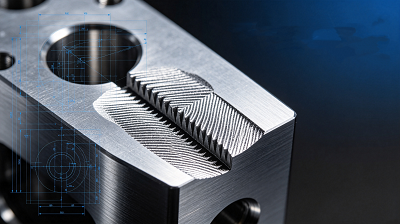
You can quickly diagnose step marks by these obvious surface characteristics:
- Tiny stepped ridges uniformly distributed across curved and inclined surfaces;
- Distinct banded layering that stands out under grazing or reflected light inspection;
- Subtle surface waviness perceptible by hand touch;
- Far more prominent on aluminum alloys, transparent engineering plastics and mirror-polished mold inserts.
Five Core Root Causes & Targeted Correction Methods
Visible step layering is almost always generated by multiple interrelated factors. Process optimization must follow a systematic inspection workflow covering the five key failure sources below.
1. Ball Screw Backlash Compensation Deviation (Primary Mechanical Cause)
Long-term operation wears the machine’s three-axis ball screws, and uncalibrated or insufficient backlash compensation creates micro displacement and tiny positional loss during toolpath direction reversals. Large flat planes and long reciprocating cutting zones will develop periodic repeating step marks as a result.
Practical Fixes
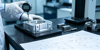
- Regularly test ball screw backlash with a dial indicator; use rigid tapping cycles to calibrate compensation values accurately;
- Activate full closed-loop backlash compensation on all 3/5-axis machines, limiting compensation volume within 0.005 mm;
- Replace severely worn ball screw assemblies promptly to eradicate micro mechanical offset at the source.
2. 5-Axis Tool Contact Point Misalignment
During A/C or B/C rotary axis rotation and direction reversal in five-axis machining, disabled RTCP (Rotational Tool Center Point) tracking or inaccurate pivot center calibration creates offset between theoretical cutting coordinates and actual tool contact points. Obvious step marks emerge at surface transition lines and deep cavity blend zones.
Practical Fixes
- Mandate RTCP tool tip tracking function for all 5-axis finishing programs;
- Precisely calibrate pivot length and rotation center, restricting calibration error under 0.002 mm;
- Cap single-segment tool axis angular variation at ≤5° to avoid abrupt, jerky rotary axis motion.
3. Unoptimized CAM Machining Toolpath Strategy
Fixed Z-level and uniform parallel raster toolpaths fail to match variable surface curvature. This creates uneven scallop height distribution, amplifies ridge texture on high-curvature radii, and generates visible texture discontinuities at toolpath junction boundaries.
Practical Fixes
- For high-curvature radii and rounded transitions: adopt flowline or curvature-adaptive variable-stepover toolpaths;
- For large, gently curved surfaces: use spiral toolpaths with auto-adjusting progressive stepover;
- Add sufficient overlap between segmented machining regions; avoid hard, unblended tool entry/exit transitions.
4. Defective CAD 3D Surface Modeling & Discontinuous Guide Curves
Modeling flaws—fragmented split surfaces, abrupt curvature jumps, polyline segmented guide curves—get infinitely magnified by generated toolpaths, directly imprinting step layering onto finished surfaces.
Practical Fixes
- Reconstruct continuous smooth CAD surfaces; delete fragmented surface patches and repair open gap edges;
- Ensure all guide curves feature G2 curvature continuity with no sharp inflection breakpoints;
- Tighten global modeling tolerance to 0.001 mm to eliminate geometric errors before programming.
5. Disabled High-Speed High-Precision Machining Mode
Machines operating under default factory settings suffer from interpolation lag, violent acceleration/deceleration shifts and slow servo response. Cumulative cutting vibration translates into micro step defects, which are most noticeable on high-gloss curved surfaces and thin-wall components.
Practical Fixes
- Activate HSM/HPC high-speed precision machining mode in the machine control panel;
- Enable advanced look-ahead interpolation with a minimum buffer of 200 program blocks to optimize servo dynamic response;
- Fine-tune servo gain parameters to match tool rigidity and reduce jerk during acceleration shifts.
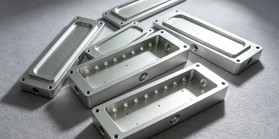
Production Case: Full Step Mark Elimination on 7075 Aluminum Glossy Medical Frame
This component serves as a core sensor mounting base for medical devices, fabricated from 7075 aerospace aluminum alloy. Strict quality standards demand flatness ≤0.02 mm on mounting planes and zero visible step layering under grazing light, to guarantee stable assembly and consistent contact performance for electronic modules.
Original Defect Situation
The workpiece’s large mounting plane and cavity vertical walls displayed clear toolpath step ridges, with periodic layered bands obvious under light inspection. Radius transition zones showed sharp discontinuous junction lines, threatening downstream assembly precision and uniform cosmetic appearance.
Root Cause Diagnosis
- Fixed uniform parallel raster toolpaths were used without curvature-adaptive stepover adjustment, creating uneven scallop heights that amplified step marks on radii;
- The original CAD model contained fragmented split surfaces, and cavity guide curves adopted polyline segmented transitions; toolpaths copied these modeling defects to form junction steps;
- The machine ran on default standard mode with only 50-block look-ahead interpolation; delayed servo response accumulated cutting vibration and micro surface steps.
Implemented Targeted Improvement Measures
- Ball screw precision calibration: Re-measured axis backlash via dial indicator, set compensation value to 0.003 mm and enabled full closed-loop compensation to eliminate reversal-point micro displacement;
- Five-axis rotary optimization: Activated RTCP tracking, limited per-segment axis angle change to 3°, and re-calibrated machine pivot rotation center;
- CAM toolpath overhaul: Switched the main mounting plane to spiral variable-stepover paths that auto-adjust residual height with curvature; replaced radius zone raster paths with continuous flowline trajectories to remove hard junction lines;
- CAD surface reconstruction: Removed fragmented patches, rebuilt all guide curves with G2 continuous curvature, and reset model tolerance to 0.001 mm;
- Machine dynamic parameter tuning: Turned on HSM high-precision mode, expanded look-ahead buffer to 300 blocks, and optimized servo gain to suppress vibration from acceleration shifts.
Final Improvement Outcome
Step marks were completely eliminated across all surfaces. No banded layering or waviness could be detected under grazing light inspection. First-pass production yield jumped to 99%, fully meeting mass production quality specifications.
Precision CNC Machining Support for Complex Custom Parts
Our workshop delivers professional 3-axis and 5-axis CNC precision machining services for cosmetic appearance parts, medical hardware, aerospace structural components and high-polish mold surfaces. We integrate machine precision calibration, advanced CAM toolpath programming and full-process quality control to minimize step marks, boost surface consistency and stabilize finished part quality—supporting both prototype development and high-volume batch manufacturing.
Conclusion
Step marks in CNC finishing are never caused by a single isolated parameter. They reflect the combined performance of machine mechanical accuracy, rotary axis control logic, CAM programming design, CAD modeling quality and machine dynamic operation modes. Eliminating layered surface defects requires cross-disciplinary optimization spanning machinery, programming and design, rather than isolated adjustments to stepover distance alone.