Complete Guide to Plastic Injection Molding: Principles, Design, Materials & Industrial Applications
1. What Exactly Is Plastic Injection Molding?
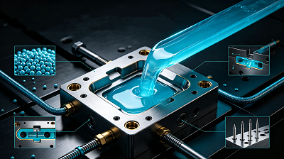
Plastic injection molding stands as the most mainstream mass-production forming technology for polymer components across global manufacturing sectors. The core logic is straightforward: solid plastic pellets are heated into a fully molten fluid state, then injected under extreme pressure into precision closed metal molds. After uniform cooling and solidification inside the cavity, finished plastic parts with consistent geometry are ejected automatically.
This process excels at manufacturing everything from tiny micro-electronic connectors to large automotive bumpers. It balances dimensional precision and production efficiency, making it the preferred solution for medium-to-high volume orders with identical product standards. Unlike subtractive machining that cuts away raw material, injection molding is a near-net-shape forming method that drastically reduces material waste.
2. Core Working Mechanism of Injection Molding
The operation logic shares similarities with large industrial syringes, relying on three core power systems: plastic melting, high-pressure injection, and mold cooling ejection.
- Raw plastic particles are fed into the machine hopper, sliding into the heating barrel; continuous heating and screw rotation turn solid pellets into homogeneous melt.
- The hydraulic or electric drive screw generates pressure ranging from 100–150 MPa, pushing molten plastic through the nozzle, sprue and runners to fill every corner of the sealed mold cavity.
- Once the cavity is fully packed, a sustained holding pressure compensates for plastic shrinkage during cooling, preventing surface dents or internal voids.
- Built-in mold cooling channels circulate water to rapidly lower the temperature of molded plastic until it hardens completely.
- The mold splits open automatically, and ejector pins push the finished part out without scratching or deformation. The mold then closes again to start the next production cycle, with each full cycle taking only several seconds for small-sized parts.
3. Full Step-by-Step Production Workflow
The entire injection molding project runs through six sequential stages from preparation to finished inspection:
Step 1: Mold Development & Fabrication
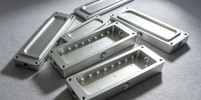
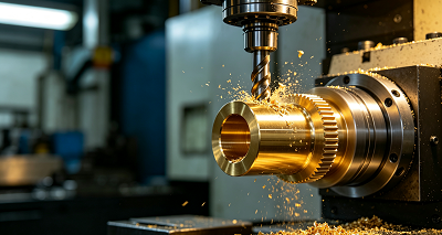
The mold acts as the "template" determining all product shapes and dimensional accuracy, which is the highest-cost component in the whole molding project. Engineers first finalize 3D part models and conduct DFM (Design for Manufacturability) analysis to eliminate unmanufacturable structures. Manufacturers then use CNC milling, EDM or 3D printing to process mold cores and cavities. Two mainstream mold materials are widely adopted: aluminum molds for short-run prototype production, and hardened steel molds for millions of mass production cycles. A complete mold includes runners, gates, cooling pipelines, vent slots and ejection systems as standard modules.
Step 2: Material Selection & Preprocessing
Material selection directly decides product mechanical performance, heat resistance and chemical stability. Designers need to evaluate core requirements including impact strength, flexibility, UV resistance, sterilization tolerance and weight limits. Most hygroscopic resins such as nylon and PC require drying before production to avoid bubbles or burn marks. Universal options include PP, ABS, nylon and PC, each with distinct physical and chemical characteristics.
Step 3: Machine Parameter Calibration & Setup
Operators install the mold onto the injection machine, align clamping plates and lock mold tightness. Next, they adjust critical process parameters: barrel temperature zones, injection speed, holding pressure, cooling cycle duration and ejection delay. A small batch of trial products is produced to test filling completeness, surface finish and dimensional tolerance before formal mass production starts.
Step 4: Molding Cycle (Melting, Injection, Holding & Cooling)
This is the core production stage. The rotating screw melts plastic evenly, then injects molten resin into the mold cavity at segmented speeds. After full filling, holding pressure continues to feed extra melt to offset thermal shrinkage. Cooling accounts for 60%–80% of the total cycle time; well-designed cooling channels ensure uniform temperature distribution to avoid warpage and uneven shrinkage.
Step 5: Automated Ejection
After cooling reaches the standard threshold, the mold half opens, and ejector plates drive ejector pins to push the solid part out of the cavity. Advanced production lines deploy robotic arms to pick parts automatically, eliminating manual contact and reducing surface scratches. Proper draft angles on part walls ensure smooth release without cracking or deformation.
Step 6: Quality Inspection & Secondary Post-Processing
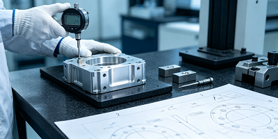
All ejected parts go through multi-level quality control: visual inspection for flash, burn marks and sink marks; dimensional measurement with calipers or CMM to verify tolerance standards; mechanical testing for strength and assembly fit. Depending on customer specifications, post-processing steps follow, including gate trimming, polishing, painting, UV coating, ultrasonic welding or assembly of auxiliary components.
4. Critical Design Rules for Molded Parts
Unreasonable part design will trigger high defect rates, raise mold costs and extend production cycles. Designers must follow these core guidelines during product development:
Dimensional Tolerance
Standard injection molding achieves a tolerance of ±0.005 inches for precision components. Tighter tolerance demands ultra-precision steel molds and stricter process control, which greatly lifts manufacturing costs. Designers must reserve shrinkage allowance according to the selected plastic resin, as each material features unique shrinkage rates after cooling.
Uniform Wall Thickness
Uneven wall thickness is the primary cause of sink marks, warpage and internal voids. The ideal design maintains consistent wall thickness across the whole part; if thickness variation is unavoidable, the difference should be controlled within 0.04–0.15 inches. Thicker sections extend cooling time and increase material consumption significantly.
Internal Corners & Structural Ribs
Sharp inner corners create concentrated stress points that weaken part durability. All inner edges should adopt rounded fillets to distribute plastic flow evenly. Ribs are thin reinforcing structures that boost rigidity without adding wall thickness; rib thickness should be 40%–60% of the main wall thickness. Overly thick ribs will leave obvious sink marks on the outer product surface.
Draft Angle
Vertical side walls must add a taper draft angle to prevent parts from sticking to the mold during ejection. The recommended baseline angle is 1°–2°; deep, narrow recesses require larger angles to avoid surface scuffs. If draft angles are missing, forced ejection will crack or deform finished products.
Undercut Structures
Undercuts create interlocking geometries that block direct ejection, requiring extra sliding mechanisms or lifters inside the mold. These complex structures push up mold manufacturing costs and lengthen cycle times. Designers should remove non-functional undercuts wherever possible to simplify mold construction.
Gate & Vent Layout
Gates are the entry points for molten plastic into cavities. Gate size and placement control flow speed, weld line location and surface aesthetics; visible consumer products usually adopt tiny hidden gates to reduce post-trimming work. Vent slots (0.01–0.03mm width) are arranged at cavity dead ends to release trapped air, eliminating gas burns and incomplete filling defects.
Ejector Pin Placement
Ejector pins are installed on the mold B-side to push out finished parts. Engineers must optimize pin positions to avoid prominent indentations on visible surfaces. Sufficient draft angles can even reduce the quantity of required ejector pins.
5. Major Variants of Injection Molding Technology
Beyond standard single-material injection molding, multiple specialized derivative processes meet diverse multi-material and hollow part demands:
Insert Molding
Pre-fabricated metal, ceramic or circuit inserts are fixed inside the mold cavity before plastic injection. Molten resin wraps tightly around inserts, forming integrated multi-material components. This process is widely used for plastic parts with embedded metal screw threads, conductive terminals and reinforcing steel sheets.
Overmolding (Dual-Shot Molding)
Two layers of different polymers are molded sequentially: a rigid hard plastic base is formed first, then soft elastomer (TPE, rubber) is overmolded onto the surface. It improves anti-slip grip for tool handles, wearable device shells and daily consumer goods, removing separate adhesive assembly procedures.
Liquid Silicone Injection Molding (LSR)
A thermosetting liquid silicone material is injected and rapidly cured inside heated molds, producing flexible, high-temperature-resistant elastic parts. LSR products feature excellent biocompatibility, making them the mainstream choice for medical gaskets, food-grade seals and waterproof electronic buffers.
Blow Molding
A special molding branch dedicated to hollow thin-wall containers. Heated plastic parison is clamped in molds, then high-pressure air inflates the material to attach to cavity walls, forming bottles, cosmetic jars and food packaging vessels with lightweight, impact-resistant properties.
Micro-Foam Injection Molding
Supercritical nitrogen or carbon dioxide is mixed with molten plastic to generate uniform microbubbles inside the part. It cuts raw material usage by 10%–30%, lowers molding pressure and reduces internal stress deformation, suitable for lightweight automotive interior panels and aerospace structural parts.
6. Common Polymer Resins & Functional Additives
Mainstream Base Resins
-
ABS (Acrylonitrile Butadiene Styrene)
Balanced toughness, low production cost, stable dimensional performance and excellent surface gloss. Widely applied in automotive interior trims, electronic housings, household appliances and toy products.
-
Nylon (Polyamide, PA)
Outstanding wear resistance, tensile strength and high-temperature tolerance. Ideal for mechanical moving parts such as gears, bearings and transmission brackets; requires strict drying before molding due to high water absorption.
-
PC (Polycarbonate)
Transparent engineering plastic with ultra-high impact resistance, good heat stability. Used for optical lenses, safety shields, electrical enclosures and automotive lamp covers, though vulnerable to surface scratches without coating.
-
PMMA (Acrylic)
Glass-level light transmittance, lightweight and easy to mold. Applied to display screens, lighting lenses and decorative transparent panels; weaker impact resistance compared to PC.
-
PP (Polypropylene)
Low-density, chemical-resistant, cost-effective flexible plastic. Perfect for mass-produced food containers, disposable medical supplies, automotive lightweight parts and packaging shells.
-
PE (Polyethylene)
Excellent flexibility and corrosion resistance, including HDPE (high rigidity) and LDPE (soft texture). Used for plastic pipes, storage containers and thin packaging films.
Functional Modification Additives
Manufacturers blend additives into base resins to customize product performance:
- PTFE (Teflon): Boost self-lubrication, reduce friction for sliding mechanical components
- Carbon Fiber: Greatly enhance stiffness and tensile strength while maintaining light weight, favored by aerospace and sports equipment
- Aramid (Kevlar): Improve impact resistance with low abrasion, adopted in high-performance auto and aviation components
- Talc & Clay Fillers: Lower raw material costs, increase rigidity and reduce shrinkage deformation
- Short/Long Glass Fiber: Upgrade tensile strength; long glass fiber delivers superior structural performance for heavy-load industrial parts
7. Key Advantages & Limitations of Injection Molding
Core Advantages
- Ultra-high mass production efficiency: After mold completion, each cycle finishes within seconds, supporting thousands of identical parts daily with fully automated lines.
- Superior dimensional precision: Complex intricate structures can be molded in one shot, stable tolerance meets automotive, medical and electronics industry standards.
- Minimal raw material waste: Sprues, runners and defective products can be recycled and remelted for secondary production, cutting material loss drastically.
- Extensive material compatibility: Supports all thermoplastics, partial thermosets and composite modified polymers with flexible performance tuning.
- Economical for large batches: High upfront mold cost is diluted over mass output, driving down per-unit manufacturing cost significantly.
- Full automation capability: Automatic feeding, injection, ejection and robotic picking reduce manual labor input and human error.
Main Disadvantages
- High initial investment: Custom precision molds require long processing cycles and high manufacturing fees, not economical for small-batch prototype orders.
- Low design flexibility post-mold completion: Modifying product geometry demands mold rework or remanufacturing, bringing extra time and capital cost.
- Long mold lead time: Complex molds often take several weeks to months to finish, delaying the overall product launch schedule.
- Inherent plastic shrinkage risk: All polymers shrink during cooling; improper mold design or parameter settings cause permanent warpage, sink marks and dimensional deviation.
- Plastic environmental footprint: Non-recyclable single-use plastic parts create waste pollution without proper recovery systems.
8. Practical Optimization Tips for Higher Yield & Lower Cost
-
Match material performance to actual usage scenarios
Avoid over-specifying high-performance expensive resins for simple low-load parts; select cost-effective materials that fully satisfy strength, temperature and chemical resistance requirements only.
-
Prioritize high-volume production planning
The economic advantages of injection molding only emerge at large order quantities. For prototypes or batches under 500 units, CNC machining or 3D printing delivers lower total cost without mold investment.
-
Optimize wall thickness uniformity
Consistent wall design shortens cooling cycles, reduces raw material consumption and eliminates most shrinkage-related defects simultaneously.
-
Simplify complex undercut and curved structures
Minimize unnecessary undercuts and deep irregular geometries to cut mold sliding mechanism costs and speed up molding cycles.
-
Adjust gate size and position reasonably
Multiple gates for large-sized parts ensure uniform melt filling; hidden small gates on visible surfaces reduce post-processing polishing workload.
-
Upgrade mold cooling and venting systems
Dense, evenly distributed cooling pipelines shorten cycle time; sufficient vent slots eliminate gas-related defects and improve product surface quality.
9. Main Industrial Sectors Using Injection Molded Components
Automotive Industry
Lightweight plastic parts replace metal to lift fuel efficiency and reduce vehicle weight. Typical products include bumpers, instrument panels, door inner panels, plastic fuel tanks, wire harness connectors and battery housing for new energy vehicles. Engineering-grade high-temperature plastics guarantee long-term service stability under engine ambient conditions.
Medical Equipment
Biocompatible, sterilizable polymer materials are widely used for single-use medical supplies and precision instruments: IV fluid bags, syringe housings, surgical tool casings, medical silicone seals and diagnostic device shells. LSR injection molding dominates flexible medical sealing components.
Food & Beverage Packaging
PP, PE and food-grade PP plastic form lightweight, low-cost packaging that resists moisture and chemical erosion: drinking bottles, disposable food containers, snack packaging sachets and storage boxes. Molded plastic replaces heavy glass and metal packaging for logistics cost reduction.
Aerospace & Aviation
High-strength low-weight composite plastic parts reduce aircraft load and maintenance frequency. PEEK, carbon-fiber-reinforced PC and modified nylon are used for cabin panels, equipment enclosures, turbine auxiliary housings and lightweight structural brackets with flame-retardant and UV-resistant properties.
Electronics & Electrical Appliances
Plastics provide insulation against electric shock and heat conduction. Core molded products include phone middle frames, charger casings, fuse boxes, circuit board supports, keyboard keycaps and household appliance outer shells. Flame-retardant modified resins meet electrical safety standards.
Consumer Daily Goods & Sports Equipment
Toothbrush handles, storage bins, toy shells, sports gear grips and cosmetic containers all rely on injection molding for mass production with rich color and surface texture options.
10. When to Choose & Avoid Injection Molding
Suitable Scenarios
- Mass production of identical plastic parts (over 1,000 pieces per order)
- Parts requiring consistent dimensional tolerance and complex integrated geometry
- Large-scale consumer goods, automotive and electronic standardized components
- Products demanding automated continuous production with low per-unit cost
Unsuitable Scenarios
- Small-batch prototype development (less than 500 units)
- Frequent iterative design changes (mold rework costs exceed alternative processing fees)
-
Ultra-large single-piece low-volume components
In these cases, CNC machining, vacuum casting or industrial 3D printing deliver faster turnaround and lower upfront investment.
Extra Chapter 1: Standard Composition of Injection Molding Equipment
Modern injection machines fall into three categories: hydraulic, all-electric and hybrid types, with five core functional modules:
- Clamping Unit: Generates massive clamping force to lock the mold tightly during injection, preventing mold separation and flash defects.
- Injection Unit: The core melting and feeding system, including feed hopper, heating barrel, rotating screw and injection nozzle, responsible for plastic plasticization and high-pressure cavity filling.
- Mold Assembly: Precision metal forming tool containing cavity, core, cooling channels and ejection structures.
- Central Control System: Touchscreen PLC controller regulating temperature, injection pressure, speed and cycle timing with real-time parameter monitoring.
- Cooling & Ejection System: Circulating water cooling pipelines for rapid solidification; ejector plates and pins to push finished parts out post-cooling.
Extra Chapter 2: Typical Molding Defects & Root Causes
- Warpage: Uneven cooling rates across part walls, inconsistent material shrinkage or unbalanced ejection force
- Sink Marks: Overly thick wall sections, insufficient holding pressure or improperly sized gate
- Flash (Burrs): Insufficient clamping force, excessive injection pressure or worn mold parting lines
- Short Shots (Incomplete Filling): Blocked vents, insufficient melt temperature or inadequate injection pressure
- Burn Marks: Trapped air inside cavity, overheating of plastic resin or too fast injection speed
Most defects can be eliminated by adjusting mold design, optimizing process parameters or switching more suitable polymer materials.
Extra Chapter 3: Actionable Ways to Cut Down Molding Expenses
- Optimize part geometry to remove redundant thick walls and complex undercuts, lowering mold processing difficulty and material consumption.
- Arrange large batch orders to leverage economies of scale and reduce unit amortized mold cost.
- Conduct regular mold maintenance to extend tool service life and avoid expensive mold replacement.
- Select cost-efficient base resins and limit high-cost functional additives to only critical performance areas.
- Recycle clean sprues and defective plastic scraps as secondary raw material to cut virgin resin purchase volume.
Custom Mold Manufacturing Service Introduction
The mold is the core asset determining molding quality and production efficiency. Our engineering team delivers one-stop custom mold development services for prototype and mass production projects:
- Fast aluminum prototype molds for small-batch verification
- Hardened steel precision molds supporting millions of production cycles
- Pre-production DFM analysis to identify design flaws early and avoid costly mold rework
- Complete mold testing, parameter tuning and after-sales technical support
We adopt CNC precision machining and EDM technology to guarantee tight dimensional accuracy, helping clients shorten product launch cycles and control overall manufacturing costs.
Final Summary
Plastic injection molding remains the backbone of modern polymer manufacturing, balancing high precision, mass efficiency and material versatility. Successful molding output relies on three key pillars: scientific part design following manufacturability rules, matching resin selection based on product application, and precise control of mold and machine process parameters.
While high initial mold investment limits small-batch use, its unit cost advantage makes it irreplaceable for standardized mass-produced components across automotive, medical, electronics and aerospace industries. Early DFM design optimization and reasonable material selection are the most effective methods to reduce defect rates and overall production expenses.
Frequently Asked Questions
Q1: Aluminum mold or steel mold — which one should I pick?
Aluminum molds suit low-melting-point resins (PP, ABS, PE) and short-run prototype batches under 10,000 pieces, with lower manufacturing cost and faster delivery. Hardened steel molds feature superior wear resistance and dimensional stability, ideal for long-term mass production over 100,000 cycles and high-temperature engineering plastics.
Q2: How long does a full injection molding cycle take?
Cycle time varies based on part size, wall thickness and material. Tiny thin-wall electronic parts complete one cycle in 5–20 seconds; thick automotive structural components require 1–3 minutes due to extended cooling periods. Cooling time accounts for the largest share of total cycle duration.
Q3: Is plastic injection molding an expensive manufacturing process?
Total cost depends on mold investment, raw material price and order volume. For small prototype batches, the high mold fee makes injection molding costly. For mass orders above several thousand pieces, the amortized mold cost per unit drops sharply, becoming far more cost-effective than CNC machining or 3D printing.