Understanding Perpendicularity in GD&T: A Complete Guide for Manufacturers
What Exactly Is Perpendicularity?
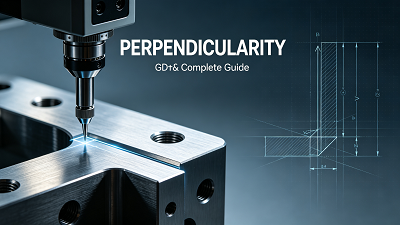
Perpendicularity is one of the orientation tolerances in the GD&T system. It governs how closely a feature approaches a perfect right angle (90°) relative to a specified datum reference. Unlike simple angular dimensions, perpendicularity provides a clear, unambiguous tolerance zone that ensures parts will function as intended when mated with other components.
In precision manufacturing, maintaining proper perpendicularity is far more than an aesthetic concern. It directly impacts load distribution, wear patterns, sealing performance, and assembly ease. Parts that fall outside their perpendicularity tolerance may fit together but create hidden stresses that lead to premature failure down the line.
The Perpendicularity Symbol
The GD&T perpendicularity symbol consists of two lines intersecting at a right angle — essentially an inverted "T" shape. In a feature control frame, this symbol is followed by the tolerance value and the datum reference letter, forming a complete specification that leaves no room for interpretation.
The Two Primary Forms of Perpendicularity Control
Perpendicularity can be applied to different types of features, and the behavior of the tolerance changes accordingly. Understanding these two categories is essential for both designers and quality inspectors.
Surface Perpendicularity
Surface perpendicularity controls the orientation of a flat surface relative to a datum plane. The tolerance zone is defined by two parallel planes that are themselves perfectly perpendicular to the datum. The entire controlled surface must fall within this space.
This type of perpendicularity is critical for components where mating surfaces must seat uniformly. Consider a flange face that needs to seal against a gasket — if the surface tilts even slightly, pressure becomes uneven and leakage occurs. Similarly, bracket mounting surfaces require perpendicularity to ensure that fastened loads distribute evenly rather than concentrating at a single edge.
Practical Example: Imagine a rectangular block with a perpendicularity callout of 0.08 mm referenced to Datum A on its side face. The tolerance zone consists of two planes, 0.08 mm apart, both at exactly 90° to Datum A. Every point on the controlled surface must lie between these two planes for the part to pass inspection.
Axis Perpendicularity
Axis perpendicularity applies to cylindrical features such as holes, pins, and shafts. Instead of controlling a surface, it governs the orientation of the feature's central axis relative to a datum.
The tolerance zone here takes the form of a cylinder — the axis of the actual feature must remain entirely within this imaginary cylindrical boundary, which itself is perfectly perpendicular to the datum reference.
This form of perpendicularity is vital for press-fit components, bearing bores, and fastener holes. A hole drilled at even a slight angle to its reference surface can cause binding, uneven wear, or complete assembly failure.
Practical Example: A hole with a 0.1 mm axis perpendicularity callout relative to Datum A has a cylindrical tolerance zone 0.1 mm in diameter. The centerline of the actual hole must stay within this cylinder throughout its entire depth.
How Tolerance Zones Work
Visualizing the tolerance zone is the key to understanding perpendicularity. For surface perpendicularity, think of two parallel "walls" that the surface must fit between. For axis perpendicularity, picture a "straw" through which the feature's centerline must pass without touching the sides.
The width or diameter of this zone equals the tolerance value specified in the feature control frame. Importantly, the tolerance zone itself is always perfectly oriented to the datum — any tilt in the actual feature is measured against this ideal reference.
Methods for Measuring Perpendicularity
Verifying perpendicularity requires the right tools and techniques. The choice of method depends on the required accuracy, the feature type, and production volume.
Coordinate Measuring Machines (CMM)
CMMs represent the gold standard for precision perpendicularity measurement. These automated machines use a touch probe to sample hundreds of points across the feature and datum surfaces. Sophisticated software then calculates the exact orientation and compares it to the nominal 90° specification.
CMMs excel with complex geometries and tight tolerances. They can measure features that are difficult or impossible to reach with manual tools, and they produce digital reports that document every measurement — essential for quality traceability in regulated industries.
Dial Indicator Setups
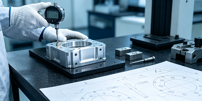
Dial indicators (or dial gauges) offer a practical, cost-effective approach for many shop-floor applications. The setup typically involves mounting the indicator on a surface plate or fixture that serves as the datum reference. As the part or indicator traverses the controlled surface, the gauge needle shows variations from the ideal orientation.
While not as precise as a CMM, dial indicators are reliable, fast, and require minimal training. They remain a workhorse in machine shops worldwide for quick go/no-go checks and in-process verification.
Precision Squares and Angle Blocks
For straightforward manual inspection, precision squares and angle blocks are indispensable tools. These hardened steel tools provide a reference 90° angle with extremely high accuracy.
Inspectors place the part against the square and observe any gap between the part surface and the tool's blade. Common techniques include the light test (holding the assembly up to a light source to see where gaps appear) and the feeler gauge method (sliding thin metal leaves into the gap to measure its size).
This approach is simple, portable, and requires no power or electronics — making it ideal for on-site checks and first-article inspections.
Perpendicularity vs. Other GD&T Controls
Perpendicularity is part of a family of orientation and form tolerances. Understanding how it relates to similar symbols prevents confusion on the shop floor.
vs. Parallelism — Parallelism and perpendicularity are two sides of the same coin. Both control orientation relative to a datum, but parallelism enforces 0° alignment (features run in the same direction) while perpendicularity enforces 90°. The tolerance zone concepts are nearly identical; only the angle changes.
vs. Straightness — Straightness is a form tolerance, not an orientation tolerance. It controls how straight a line or axis is without any reference to a datum. A feature can be perfectly straight but tilted relative to its reference — straightness wouldn't catch this, but perpendicularity would.
vs. Angularity — Angularity is the general case of which perpendicularity is a specific instance. While perpendicularity always refers to a 90° angle, angularity can specify any angle between 0° and 90°. When the angle is exactly 90°, perpendicularity is the preferred callout because it's more explicit and universally recognized.
vs. Position — Position controls the location of a feature, while perpendicularity controls only its orientation. A hole can be in the right spot but drilled at an angle (good position, bad perpendicularity) or perfectly straight but in the wrong place (good perpendicularity, bad position). Often both are specified together for critical features.
Where Perpendicularity Matters Most
Perpendicularity appears across virtually every industry that produces precision parts. Here are some of the most common applications:
- Bracket and mounting surfaces — In structural components, perpendicularity ensures that fastened joints distribute loads evenly rather than creating bending moments.
- Bearing housings — A bearing bore that isn't perpendicular to its mounting face causes the shaft to run at an angle, leading to rapid wear, noise, and premature failure.
- Fixture and jig design — Tooling that locates workpieces must itself be perpendicular to reference surfaces. Any error multiplies through every part produced with that fixture.
- Sealing surfaces — Flanges, manifolds, and gasket faces rely on perpendicularity to maintain uniform compression across the entire sealing area.
- Optical and sensor mounts — In precision instruments, even sub-degree angular errors can throw alignment off by millimeters at distance.
Common Pitfalls and Best Practices
Designers and manufacturers often run into the same issues with perpendicularity specifications. Avoiding these common mistakes saves time, reduces scrap, and improves part performance.
Don't over-specify. Tighter perpendicularity than necessary drives up cost exponentially. A 0.05 mm tolerance might sound impressive, but if 0.2 mm works perfectly for the application, you're wasting money.
Always specify the datum clearly. Perpendicularity without a clear datum reference is meaningless. Make sure the feature control frame explicitly references the appropriate datum plane or axis.
Consider feature size with axis perpendicularity. For holes and pins, remember that the tolerance zone is cylindrical. The larger the feature diameter relative to its depth, the more angular deviation is allowed for a given tolerance value.
Use MMC modifiers where appropriate. When perpendicularity is applied at Maximum Material Condition (MMC), the tolerance increases as the feature departs from MMC size. This can improve manufacturability without sacrificing function — but only if the application allows it.
Final Thoughts
Perpendicularity is more than just another GD&T symbol — it's a fundamental control that ensures parts fit together and work as designed. Whether you're a designer drafting tolerances, a machinist setting up a job, or a quality engineer verifying parts, a solid grasp of perpendicularity principles is essential.
By choosing the right type of perpendicularity control, setting realistic tolerances, and selecting appropriate measurement methods, manufacturers can achieve the precision they need without unnecessary cost.
Frequently Asked Questions
Does perpendicularity control the location of a feature?
No. Perpendicularity is purely an orientation control. It governs the angle of a feature relative to a datum but says nothing about where that feature sits in space. For location control, use the position symbol instead.
Can a single feature have multiple perpendicularity callouts?
Absolutely. In three-dimensional space, a surface or axis can be perpendicular to two or three different datum references simultaneously. Each callout controls orientation in a different plane.
How do machinists achieve tight perpendicularity?
Strategies include using precision fixtures and vises, taking light finishing cuts, ensuring the machine tool itself is properly trammed, and using high-quality cutting tools with minimal deflection.
Is perpendicularity the same as squareness?
In everyday language, yes — they mean the same thing. In GD&T terminology, "perpendicularity" is the standard term used in official standards and feature control frames.