Common CNC Machining Defects: Causes, Prevention and Optimization Strategies
Surface Quality Defects
Surface defects are among the most visible and frequently encountered issues in CNC machining. These defects not only affect the aesthetic appearance but can also compromise functional performance, especially in parts requiring tight seals or wear resistance.
Common Surface Defects and Causes
- Tool marks and chatter marks: Visible periodic patterns on the machined surface caused by tool vibration, improper cutting parameters, or worn cutting edges.
- Burrs and sharp edges: Unwanted material projections along cut edges, resulting from tool deflection, insufficient chip evacuation, or improper feed rates.
- Scratches and gouges: Surface damage caused by chip recutting, tool breakage fragments, or improper part handling during machining.
- Poor surface roughness: Failure to meet Ra requirements due to incorrect tool selection, excessive feed per tooth, or inadequate coolant application.
Prevention and Optimization Methods
- Select appropriate tool geometries and coatings based on the workpiece material to reduce cutting forces and minimize tool wear.
- Optimize cutting parameters — balance spindle speed, feed rate, and depth of cut to avoid chatter while maintaining productivity.
- Implement proper tool change schedules and use tool condition monitoring to detect wear before it affects surface quality.
- Ensure adequate coolant flow and pressure to flush chips away from the cutting zone and reduce thermal effects on the surface.
- Add a dedicated finishing pass with lighter cuts and higher feed rates to improve final surface quality.
Dimensional Accuracy Defects
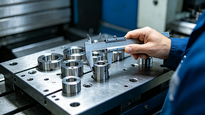
Dimensional defects occur when the finished part does not meet the specified tolerances. These errors can stem from multiple sources throughout the machining process and are particularly critical for parts requiring precise assembly or interchangeability.
Types and Root Causes
- Tool deflection errors: When cutting forces cause the tool to bend away from the intended path, resulting in undersized features or tapered walls.
- Thermal expansion errors: Heat generated during cutting causes the tool, workpiece, and machine spindle to expand, leading to dimensional drift over time.
- Fixture positioning errors: Inaccurate part location due to worn fixture components, improper clamping, or debris on locating surfaces.
- Machine geometric errors: Inherent inaccuracies in the machine tool’s axes, including backlash, lead screw errors, and axis misalignment.
Prevention and Optimization Methods
- Use high-rigidity tool holders and minimize tool overhang to reduce deflection; perform roughing and finishing with separate tools and parameters.
- Allow warm-up time for the machine spindle and implement thermal compensation strategies; maintain consistent coolant temperature.
- Regularly inspect and maintain fixtures; implement proper part cleaning procedures before clamping to prevent debris interference.
- Schedule periodic machine calibration and laser compensation to maintain geometric accuracy within acceptable limits.
- Use in-process measurement and probe systems to verify dimensions mid-cycle and apply offsets automatically.
Deformation Defects
Deformation defects involve changes in the part’s shape or geometry that occur during or after machining. These defects are especially problematic for thin-walled parts, large components, and materials with high residual stress.
Common Deformation Issues
- Cutting force-induced deformation: The part deflects under cutting forces, causing spring-back that results in dimensional errors and inconsistent wall thickness.
- Residual stress deformation: Internal stresses released during material removal cause the part to warp or twist, often becoming noticeable only after unclamping.
- Clamping deformation: Excessive clamping force distorts the part, which springs back after release, leading to out-of-tolerance dimensions.
- Thermal deformation: Uneven heating during machining creates thermal gradients that cause temporary or permanent shape distortion.
Prevention and Optimization Methods
- Design parts with adequate rigidity; add temporary support structures or ribs that can be removed after machining.
- Use stress-relieved material or perform a pre-machining stress relief operation to stabilize the workpiece before finishing.
- Optimize clamping strategies — use soft jaws, vacuum chucks, or low-melting-point alloy fillers to distribute clamping force evenly.
- Implement high-speed, low-depth-of-cut machining strategies to reduce cutting forces and minimize part deflection.
- Sequence operations strategically — remove material symmetrically and allow the part to rest between roughing and finishing operations.
Case Study Analysis: Defect Reduction for Medical Device Stainless Steel Component
The project involves a surgical instrument component made from 316L stainless steel, measuring approximately 85 × 42 × 18 mm. The part requires a mirror surface finish (Ra 0.2) on critical surfaces and tight dimensional tolerances of ±0.01 mm. Initial production runs experienced high defect rates, with over 35% of parts failing inspection.
Initial Defect Analysis
Upon reviewing the first batch of parts, quality control identified three primary defect categories that were causing the high rejection rate:
1. Surface Chatter Marks on Finished Surfaces
The critical mating surfaces exhibited visible chatter marks with a periodic pattern, measuring approximately 0.8 mm between peaks. Surface roughness readings varied between Ra 0.4 and Ra 0.8, failing to meet the required Ra 0.2 specification. Investigation revealed that the finishing operation was using a 6 mm end mill with excessive overhang (48 mm) in a standard collet holder, resulting in unstable cutting conditions.
2. Dimensional Drift in Deep Hole Features
Several precision holes with diameters of 2.5 mm and depths of 15 mm showed consistent taper — the entrance diameter measured 2.51 mm while the bottom measured 2.48 mm, exceeding the ±0.01 mm tolerance. The issue was traced to tool deflection during the deep drilling operation, compounded by insufficient pecking cycles that caused chip packing in the flutes.
3. Post-Unclamping Warpage
Parts that passed dimensional inspection while still fixtured often failed after removal, with flatness deviations of up to 0.08 mm across the 85 mm length. This warpage was caused by residual stresses in the stainless steel bar stock being released asymmetrically during material removal, combined with excessive clamping force from the vise jaws.
Optimization Plan and Implementation Results
Working closely with the customer’s engineering team, we implemented the following process improvements without requiring any design changes to the part:
Optimization 1: Rigidity Upgrade for Finishing Operations
Replaced the standard collet holder with a hydraulic chuck that provides 3x more clamping rigidity, and reduced tool overhang from 48 mm to 32 mm by using a shorter tool length. The finishing parameters were also adjusted — spindle speed increased by 25% while feed per tooth decreased by 30%, shifting the cutting dynamics away from the chatter frequency range.
Result: Surface chatter was completely eliminated, and surface roughness consistently achieved Ra 0.15–0.2, meeting the specification with margin.
Optimization 2: Step-Drilling Strategy with Enhanced Chip Evacuation
Replaced the single-shot deep drilling approach with a three-step drilling sequence — pilot drill, 2.0 mm pre-drill, and final 2.5 mm finish drill — with increased pecking frequency and higher-pressure coolant delivery through the tool. This reduced the cutting forces on the final drill by approximately 60% and ensured consistent chip evacuation throughout the hole depth.
Result: Hole taper was reduced from 0.03 mm to less than 0.005 mm, well within the tolerance requirement. Tool life also improved by 2.5x due to reduced cutting loads.
Optimization 3: Stress Relief and Improved Fixturing
Added a low-temperature stress relief cycle (2 hours at 280°C) between roughing and finishing operations to stabilize the material. The fixturing was also upgraded — replaced the standard steel vise jaws with soft aluminum jaws machined to match the part profile, and reduced clamping force by 40% using a torque-controlled vise.
Result: Post-unclamping warpage dropped from 0.08 mm to less than 0.015 mm, and flatness requirements were consistently met.
Comparison of Quality Data Before and After Optimization
|
Item
|
Before Optimization
|
After Optimization
|
Improvement
|
|---|---|---|---|
|
First-pass yield rate
|
64.5%
|
97.2%
|
+32.7 percentage points
|
|
Surface roughness (Ra)
|
0.4–0.8 μm
|
0.15–0.2 μm
|
60–75% improvement
|
|
Hole taper error
|
0.03 mm
|
<0.005 mm
|
83% reduction
|
|
Post-unclamping warpage
|
0.08 mm
|
<0.015 mm
|
81% reduction
|
|
Average tool cost per part
|
$1.85
|
$0.92
|
50% reduction
|
Quality Optimization Recommendations
Based on the above case analysis, the following general recommendations can be made for reducing CNC machining defects:
- Prioritize system rigidity: Evaluate the entire machining system — machine, tool holder, tool, and fixture — for rigidity. Deflection and vibration are the root causes of many surface and dimensional defects.
- Implement process verification: Use first-article inspection and in-process probing to catch issues early rather than discovering them after the entire batch is machined.
- Address residual stress proactively: For critical or thin-walled parts, plan for stress relief operations and strategic machining sequences that minimize asymmetric material removal.
- Optimize cutting data scientifically: Don’t rely solely on handbook values — test and optimize parameters for your specific machine, tooling, and material combination to find the stable cutting window.
Quality Assurance in Precision Machining
Achieving consistent quality in CNC machining requires more than just good equipment — it demands a systematic approach to quality assurance that spans every stage of the production process. From initial design review to final inspection, comprehensive quality management is essential for minimizing defects and ensuring reliable part performance.
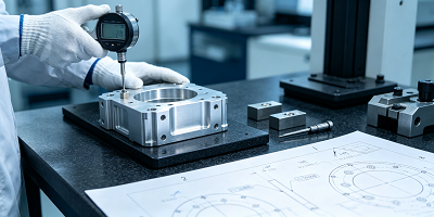
Advanced inspection equipment — including coordinate measuring machines (CMMs), optical comparators, and surface profilometers — combined with rigorous process control and DFM (Design for Manufacturability) feedback, ensures that every part meets or exceeds specifications. By integrating quality planning into the earliest stages of each project, manufacturers can avoid costly defects, reduce production risks, and achieve consistent, reliable results from prototype to full production.
Conclusion
While CNC machining is capable of producing extremely precise and high-quality parts, achieving consistent results requires a systematic approach to defect prevention. Surface quality issues, dimensional errors, and deformation defects are among the most common challenges, but each has identifiable root causes and proven solutions.
Through careful process planning, proper tooling selection, optimized cutting parameters, and proactive quality control, manufacturers can dramatically reduce defect rates and improve overall efficiency. The case study demonstrates that even significant quality issues can often be resolved with targeted process improvements — without requiring costly design changes.
By partnering with an experienced machining supplier that understands defect mechanisms and optimization strategies, product teams can ensure that their parts are manufactured right the first time, every time.