Next-Generation Impeller Manufacturing: AI-Driven Digital Twin + Hybrid Additive-Subtractive Machining for New Energy Automotive Turbochargers
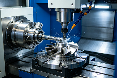
The Evolution of Impeller Design: From Conventional to Topology-Optimized
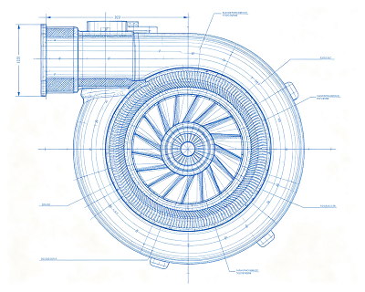
The design philosophy behind automotive impellers has undergone a dramatic shift in the NEV era. Traditional turbocharger impellers followed established hydrodynamic profiles optimized for steady-state engine operation. Today's e-turbo systems, however, operate across far broader RPM ranges and require instant response characteristics.
Key Design Evolution Drivers
- Wider Operating Envelope: E-turbos spin from 0 to 200,000 RPM in milliseconds, requiring blades optimized for both low-speed torque and high-speed efficiency
- Thermal Cycling Stress: Hybrid powertrains experience more frequent temperature fluctuations, demanding superior fatigue resistance
- Weight Reduction Mandates: Every gram of rotating mass affects throttle response and energy efficiency
- Aerodynamic Optimization: Computational Fluid Dynamics (CFD) combined with generative design produces blade profiles unachievable through traditional engineering methods
Modern topology-optimized impellers feature back-swept blade tips, variable thickness profiles, and integrated hub structures that maximize aerodynamic efficiency while minimizing material usage. These design advances, however, create new manufacturing challenges that conventional 5-axis machining struggles to address efficiently.
Material Innovation: Why Titanium Alloys Dominate NEV Turbochargers
The shift from aluminum to titanium alloys represents one of the most significant material transitions in automotive turbocharger history. While aluminum alloys like 7075-T6 remain suitable for low-boost applications, high-performance NEV turbo systems require materials that can withstand extreme operating conditions.
Material Comparison: Aluminum vs. Titanium
|
Property
|
Aluminum 7075-T6
|
Titanium Ti-6Al-4V
|
|---|---|---|
|
Density
|
2.81 g/cm3
|
4.43 g/cm3
|
|
Maximum Operating Temp
|
~250°C
|
~600°C
|
|
Tensile Strength
|
505 MPa
|
950 MPa
|
|
Fatigue Resistance
|
Moderate
|
Excellent
|
|
Corrosion Resistance
|
Good
|
Exceptional
|
|
Machining Difficulty
|
Easy
|
Very Difficult
|
Titanium aluminide (TiAl) alloys represent the cutting edge, offering 40% lower density than nickel-based superalloys while maintaining high-temperature strength. However, their extreme brittleness and machining difficulty make them suitable only for the most demanding aerospace and high-end automotive applications.
Limitations of Traditional 5-Axis Machining for Titanium Impellers
While 5-axis CNC machining has been the standard for high-precision impeller production for decades, it faces fundamental limitations when applied to titanium alloy components with modern complex geometries:
1. Material Removal Inefficiency
Titanium's low thermal conductivity (approximately 1/5 that of steel) causes heat to concentrate at the cutting edge, leading to rapid tool wear and requiring conservative feed rates. For a typical 150mm titanium impeller, traditional 5-axis machining can remove up to 85% of the original billet weight, translating to 12-18 hours of machining time and significant tool costs.
2. Tool Path Planning Complexity
Modern topology-optimized blades feature variable twist angles, back-swept tips, and thin trailing edges that require constant tool axis reorientation. Traditional CAM systems, even with impeller-specific modules, still rely heavily on operator experience to avoid gouging, undercuts, and tool interference in narrow blade passages.
3. Vibration and Chatter Challenges
Titanium's high strength-to-weight ratio, combined with thin blade structures, creates chatter-prone machining conditions. Traditional trial-and-error approaches to parameter optimization result in lengthy setup times and inconsistent surface finishes.
4. Quality Control Bottlenecks
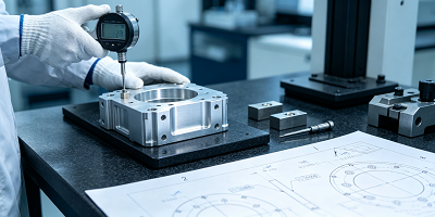
Verifying complex blade profiles requires coordinate measuring machines (CMM) with specialized scanning probes, adding significant inspection time. Offline inspection also means that errors are often discovered only after machining is complete, leading to costly scrap and rework.
Innovation 1: Digital Twin + AI-Powered Machining Optimization
The integration of digital twin technology with AI-driven optimization represents a paradigm shift in how titanium impellers are manufactured. Unlike traditional CAM software that generates static toolpaths based on geometry alone, digital twin systems create dynamic, real-time virtual replicas of the entire machining process.
How Digital Twin Machining Works
A complete digital twin for impeller machining integrates multiple data layers:
- Machine Kinematic Model: Virtual replica of the 5-axis machine's mechanical structure, including axis limits, spindle characteristics, and error mapping
- Tooling Digital Twin: Real-time tool wear prediction based on cutting forces, temperature, and material removal rates
- Workpiece Deformation Model: Finite element analysis of workpiece deflection under cutting forces, especially critical for thin titanium blades
- Process Parameter Model: AI-optimized cutting parameters that adapt to real-time machining conditions
AI-Driven Optimization Capabilities
Advanced machine learning algorithms analyze thousands of data points per second to optimize the machining process:
- Adaptive Feed Rate Control: AI adjusts feed rates in real-time based on spindle load and vibration signatures, maintaining maximum safe cutting speeds
- Predictive Tool Wear Compensation: The system predicts tool degradation and automatically offsets tool paths to maintain dimensional accuracy
- Chatter Suppression: AI identifies chatter frequencies and adjusts spindle speed or tool orientation to suppress vibration before it affects surface quality
- Thermal Error Compensation: Real-time thermal expansion modeling compensates for machine and workpiece temperature variations
Early industry implementations have demonstrated 30-40% reductions in machining time for titanium impellers, along with 50% improvements in tool life and more consistent surface quality across production batches.
Innovation 2: Hybrid Additive-Subtractive Manufacturing Process
The second transformative innovation in impeller manufacturing is the integration of additive and subtractive processes into a single hybrid manufacturing workflow. This approach combines the design freedom of 3D printing with the precision and surface quality of CNC machining.
The Hybrid Manufacturing Workflow
Unlike traditional "near-net-shape" approaches that use separate machines for additive and subtractive steps, modern hybrid systems perform both operations on a single machine platform, eliminating re-fixturing errors and reducing lead times.
Step 1: Pre-Machined Core
The process begins with a precision-machined hub core manufactured from forged titanium bar stock. This core provides the critical mounting interfaces and structural foundation, ensuring mechanical properties equivalent to fully wrought components.
Step 2: Additive Blade Deposition
Using Directed Energy Deposition (DED) or Laser Metal Deposition (LMD) technology, the system builds up blade structures layer by layer directly onto the machined hub. Key advantages include:
- Material usage efficiency: 70-80% less material waste compared to billet machining
- Design freedom: Ability to create internal cooling channels and undercut features impossible with conventional milling
- Graded materials: Potential for functionally graded material properties across the blade
Step 3: In-Process Machining
After each additive layer or section, the machine switches to milling mode to machine critical surfaces to final tolerance. This "deposit-and-machine" cycle ensures that all surfaces remain accessible to cutting tools, even for highly complex blade geometries.
Step 4: Final Finishing
The complete impeller undergoes final 5-axis finishing of all aerodynamic surfaces, followed by polishing and surface treatment to achieve required surface roughness and fatigue performance.
Hybrid vs. Traditional Manufacturing Comparison
|
Metric
|
Traditional 5-Axis
|
Hybrid Add-Sub
|
|---|---|---|
|
Material Waste
|
70-85%
|
15-25%
|
|
Total Lead Time
|
5-7 days
|
2-3 days
|
|
Design Complexity
|
Limited by tool access
|
Near-unlimited
|
|
Tooling Cost
|
High (specialty end mills)
|
Medium (standard tools)
|
|
Surface Finish
|
Ra 0.4-0.8 μm
|
Ra 0.4-0.8 μm (after finish machining)
|
|
Low-Volume Cost
|
High
|
Medium-High
|
Case Study: Ti-6Al-4V E-Turbo Impeller for New Energy Vehicles
This project involved manufacturing a high-performance electric turbocharger impeller for a leading NEV manufacturer. The component required exceptional precision, fatigue resistance, and fast turnaround for prototype validation.
Project Overview
|
Material
|
Ti-6Al-4V (Grade 5) Titanium Alloy
|
|
Impeller Diameter
|
156 mm
|
|
Blade Configuration
|
7 main blades + 7 splitter blades
|
|
Minimum Blade Thickness
|
0.35 mm (trailing edge)
|
|
Surface Roughness Requirement
|
Ra 0.4 μm (blade surfaces)
|
|
Dimensional Tolerance
|
±0.01 mm (profile tolerance)
|
|
Production Quantity
|
12 prototype pieces
|
|
Total Project Timeline
|
10 days
|
Manufacturing Process Applied
Phase 1: Digital Twin Setup & Optimization
Before any metal was cut, a complete digital twin of the machining process was created. AI algorithms optimized tool paths based on:
- Finite element analysis of blade deflection under cutting loads
- Predicted tool wear patterns for titanium machining
- Thermal expansion models for both workpiece and machine tool
- Chatter stability lobe diagrams specific to the machine-spindle-tool combination
This pre-processing phase reduced programming time from the typical 3-4 days to just 8 hours and identified potential interference issues that would have required on-machine debugging.
Phase 2: Hybrid Manufacturing Execution
The impellers were produced using a hybrid DED-5-axis milling approach:
- Hub Machining: Ti-6Al-4V bar stock was turned and milled to create the precision hub core with mounting interfaces
- Blade Deposition: DED heads built up blade structures using Ti-6Al-4V powder, achieving 99.8% density
- Semi-Finish Milling: 5-axis milling removed excess material and established blade profiles to within 0.2mm of final dimensions
- AI-Optimized Finishing: Final blade surfaces were machined with AI-adaptive feed rates, maintaining constant chip load and minimizing vibration
Phase 3: Post-Processing & Inspection
Each impeller underwent:
- Hot isostatic pressing (HIP) to ensure full densification of deposited material
- Vibratory polishing to achieve Ra 0.4 μm surface finish on blade surfaces
- 3D structured light scanning for full geometry verification
- CMM inspection of critical mounting dimensions
- Dye penetrant testing for surface defect detection
Project Results
The hybrid digital twin approach delivered impressive results compared to traditional manufacturing methods:
- 45% reduction in total manufacturing time
- 65% reduction in material waste (from 82% to 29%)
- 100% first-pass yield (zero scrap parts, compared to typical 15-20% scrap rate for titanium impellers)
- Consistent surface quality across all 12 pieces, with Ra values ranging from 0.32 to 0.38 μm
- All dimensional tolerances met or exceeded customer specifications
Digital Quality Control: Beyond Traditional Inspection
The digital transformation of impeller manufacturing extends beyond the machining process itself to quality control and inspection. Modern digital quality systems integrate inspection data directly into the manufacturing digital thread, creating closed-loop feedback systems.
In-Process Metrology
Advanced machine tools now integrate on-machine measurement systems that inspect critical features during the machining process, not just after completion.
- Touch Probes with Scanning Capability: High-speed scanning probes capture thousands of data points across blade surfaces
- Laser Displacement Sensors: Non-contact measurement for thin, deflection-prone blade edges
- Adaptive Machining Feedback: Measurement data feeds back into the CNC controller in real-time
AI-Powered Visual Inspection
Machine vision systems powered by deep learning algorithms detect surface defects, tool marks, and surface anomalies that human inspectors might miss. These systems reduce inspection time by 70% compared to manual methods.
Digital Thread and Traceability
Every impeller produced in a digital twin-enabled environment comes with a complete digital birth certificate, including full process parameter history, real-time sensor data, 3D scan data, and material traceability from raw stock to finished component.
Future Trends in Impeller Manufacturing
As we look ahead, several emerging technologies promise to further revolutionize impeller manufacturing:
1. Generative Design + AI Manufacturing Co-Optimization
The next frontier is co-optimization of design and manufacturing processes. Instead of designing a part and then figuring out how to make it, AI systems will simultaneously optimize both aerodynamic performance and manufacturability, creating designs that push the boundaries of what is possible while remaining practical to produce.
2. Multi-Material Functionally Graded Impellers
Advances in additive manufacturing will enable impellers with functionally graded material properties - high-temperature resistant alloys at the blade tips, lightweight materials at the hub, and smooth transitions in between. This will enable performance improvements that are impossible with single-material construction.
3. Autonomous Manufacturing Cells
Fully autonomous manufacturing cells will combine digital twin technology, AI optimization, and robotic material handling to operate lights-out, 24/7, with minimal human intervention. These cells will be capable of self-optimization, predictive maintenance, and automatic quality correction.
4. In-Situ Material Property Monitoring
Emerging sensor technologies will enable real-time monitoring of material microstructure and mechanical properties during the manufacturing process, ensuring that every part meets performance specifications without the need for destructive testing.
Conclusion
The manufacturing of high-performance impellers for new energy vehicles is undergoing a profound transformation driven by two complementary innovations: AI-powered digital twin optimization and hybrid additive-subtractive manufacturing processes.
Digital twin technology moves beyond static toolpath generation to create dynamic, real-time optimization of the entire machining process. AI algorithms adapt to changing conditions, predict tool wear, suppress chatter, and compensate for thermal errors - all in real-time. This results in faster machining times, longer tool life, and more consistent quality.
Hybrid additive-subtractive manufacturing addresses the fundamental inefficiency of traditional billet machining by building up material only where needed and then machining to final precision. This dramatically reduces material waste, enables design features previously impossible, and shortens lead times for prototype and low-volume production.
Together, these technologies are enabling a new generation of titanium alloy impellers that meet the demanding requirements of electric and hybrid vehicle turbochargers - delivering higher performance, lighter weight, and greater reliability than ever before.
As these technologies continue to mature and become more accessible, we can expect to see them transform not just impeller manufacturing, but the entire precision components industry.